|
|
|
PDF QT510 Data sheet ( Hoja de datos )
| Número de pieza | QT510 | |
| Descripción | QWHEEL TOUCH SLIDER IC | |
| Fabricantes | QUANTUM | |
| Logotipo | ||
Hay una vista previa y un enlace de descarga de QT510 (archivo pdf) en la parte inferior de esta página. Total 14 Páginas | ||
|
No Preview Available !
www.DataSheet4U.com
lQ
QT510
QWHEEL™ TOUCH SLIDER IC
z Rotary finger-touch ‘wheel’ slider control
z Extremely simple circuit - no external active components
z Completely passive sensing element: no moving parts
z Compatible with clear ITO over LCD construction
z SPI slave-mode interface
z Self-calibration and drift compensation modes
z Proximity sensing for wake up function
z Spread-spectrum operation for optimal EMC compliance
z 2.5 - 5.5V single supply operation; very low power
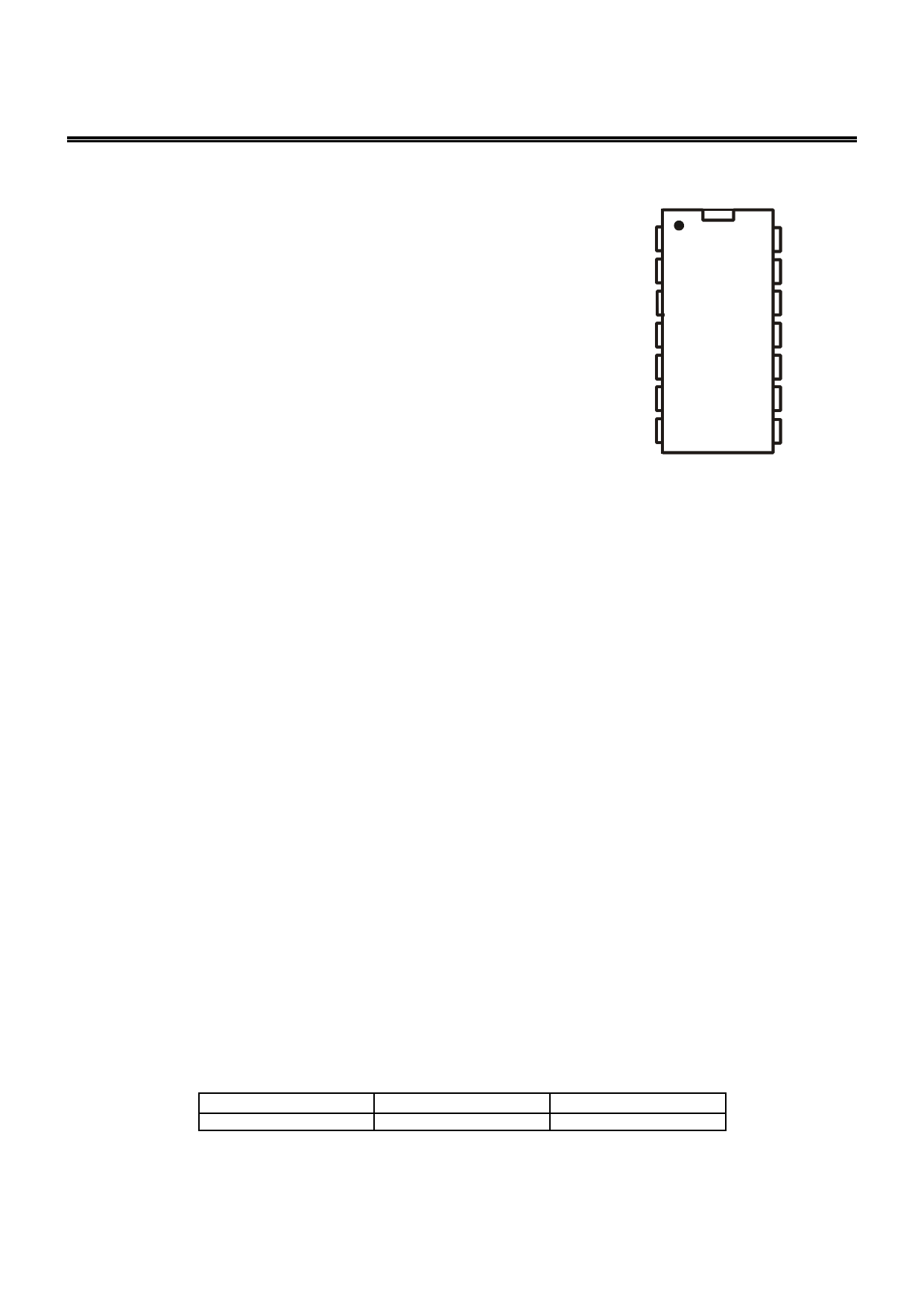
z 14-pin SOIC and TSSOP Pb-free packages
z Inexpensive, simple 1-sided PCB construction possible
z E510 reference design board available
VDD
SDO
/SS
SCLK
SNS3B
SNS3A
SNS2B
1 14
2 13
3 QT510 12
4 11
5 10
69
78
GND
DRDY
PROX
SDI
SNS1A
SNS1B
SNS2A
APPLICATIONS
y Personal electronics
y Appliance controls
y Shaft encoders
y Automotive controls
The QT510 QSlide™ IC is a new type of rotary capacitive touch ‘slider’ sensor IC based on Quantum’s patented
charge-transfer methods. This unique IC allows designers to create speed or volume controls, menu bars, and other more
exotic forms of human interface on the panel of an appliance. Generally it can be used to replace any form of rotary knob,
through a completely sealed panel.
The device uses a simple, inexpensive resistive sensing element between three connection points. The sense element can be
circular or any polygon shape. The sense element can also be used as a proximity sensor out to several centimeters, to wake
up an appliance or display from a sleep mode in a dramatic fashion.
The QT510 can report a single rapid touch anywhere along the sense element, or, it can track a finger moving along the wheel
surface in real time. The device self-calibrates under command from a host controller.
This device uses three channels of simultaneous sensing across a resistive element to determine finger position, using
mathematical analysis. A positional accuracy of 5% (or better) is relatively easy to achieve.
The acquisitions are performed in a burst mode which uses proprietary spread-spectrum modulation for superior noise
immunity and low emissions.
The output of the QT510 can also be used to create discrete controls in a circle, by interpreting sets of number ranges as
buttons. For example, the number range 0..19 can be button A, 30..49 button B, 60..79 button C etc. Continuous wheel action
and discrete controls can be mixed on a single element, or, the element can be reinterpreted differently at different times, for
example when used below or on top of an LCD to act as a menu input device that dynamically changes function in context. The
device is compatible with ITO (Indium Tin Oxide) overlays on top of various displays or simply to provide for a backlighting
effect.
TA
-400C ~ +850C
LQ
AVAILABLE OPTIONS
SO-14
QT510-ISG
TSSOP-14
QT510-ISSG
Copyright © 2004 QRG Ltd
QT510 R6.04/0505
1 page 
To assist with this problem, the QT510 waits 500µs after
coming out of sleep mode before acquiring to allow power to
fully stabilize. This delay is not present before an acquisition
burst if there is no preceding sleep state.
Use an oscilloscope to verify that Vdd has stabilized to within
5mV or better of final settled voltage before a burst begins.
2.5 PCB Layout and Mounting
The E510 PCB layout (Figure 1-3) should be followed if
possible. This is a 1-sided board; the blank side is simply
adhered to the inside of a 2mm thick (or less) control panel.
Thicker panels can be tolerated with additional position error
due to capacitive ‘hand shadow’ effects and will also have
poorer EMC performance.
This layout uses 18 copper pads connected with intervening
series resistors in a circle. The finger interpolates between
the copper pads (if the pads are narrow enough) to make a
smooth, 0..127 step output with no apparent stair-casing. The
lateral dimension along the centre of each electrode should
be no wider than the expected smallest diameter of finger
touch, to prevent stair-casing of the position response (if that
matters).
Other geometries are possible, for example triangles and
squares. The wheel can be made in various diameters up to
at least 80mm. The electrode width should be about 12mm
wide or more, as a rule.
The SMT components should be oriented perpendicular to
the direction of bending so that they do not fracture when the
PCB is flexed during bonding to the panel.
Additional ground area or a ground plane on the PCB will
compromise signal strength and is to be avoided. A single
sided PCB can be made of FR-2 or CEM-1 for low cost.
‘Handshadow’ effects: With thicker and wider panels an
effect known as ‘handshadow’ can become noticeable. If the
capacitive coupling from finger to electrode element is weak,
for example due to a narrow electrode width or a thick, low
dielectric constant panel, the remaining portion of the human
hand can contribute a significant portion of the total
detectable capacitive load. This will induce an offset error,
which will depend on the proximity and orientation of the hand
to the remainder of the element. Thinner panels and those
with a smaller diameter will reduce this effect since the finger
contact surface will strongly domina te the total signal, and the
remaining handshadow capacitance will not contribute
significantly to create an error offset.
PCB Cleanliness: All capacitive sensors should be treated
as highly sensitive circuits which can be influenced by stray
conductive leakage paths. QT devices have a basic
resolution in the femtofarad range; in this region, there is no
such thing as ‘no clean flux’. Flux absorbs moisture and
becomes conductive between solder joints, causing signal
drift and resultant false detections or temporary loss of
sensitivity. Conformal coatings will trap in existing amounts of
moisture which will then become highly temperature
sensitive.
The designer should specify ultrasonic cleaning as part of the
manufacturing process, and in extreme cases, the use of
conformal coatings after cleaning.
2.6 ESD Protection
Since the electrode is always placed behind a dielectric
panel, the IC will be protected from direct static discharge.
However even with a panel transients can still flow into the
electrode via induction, or in extreme cases via dielectric
breakdown. Porous materials may allow a spark to tunnel
right through the material. Testing is required to reveal any
problems. The device has diode protection on its terminals
which will absorb and protect the device from most ESD
events; the usefulness of the internal clamping will depending
on the panel's dielectric properties and thickness.
One method to enhance ESD suppression is to insert
resistors Rs1, Rs2 and Rs3 in series with the element as
shown in Figure 1-1; these are typically 4.7K but can be as
high as 10K ohms.
Diodes or semiconductor transient protection devices or
MOV's on the electrode traces are not advised; these devices
have extremely large amounts of nonlinear parasitic
capacitance which will swamp the capacitance of the
electrode and cause false detections and other forms of
instability. Diodes also act as RF detectors and will cause
serious RF immunity problems.
See also next section.
2.7 EMC and Related Noise Issues
External AC fields (EMI) due to RF transmitters or electrical
noise sources can cause false detections or unexplained
shifts in sensitivity.
The influence of external fields on the sensor can be reduced
by means of the Rs series resistors described in Section 2.6.
The Cs capacitor and the Rs resistors (Figure 1-1) form a
natural low-pass filter for incoming RF signals; the roll-off
frequency of this network is defined by -
FR
=
1
2✜R S C S
If for example Cs = 47nF, and Rs = 4.7K, the EMI rolloff
frequency is ~720 Hz, which is much lower than most noise
sources (except for mains frequencies i.e. 50 / 60 Hz). The
resistance from the sensing element itself is actually much
higher on average, since the element is typically 50K ~ 100K
ohms between connection points.
Rs and Cs must both be placed very close to the body of the
IC so that the lead lengths between them and the IC do not
form an unfiltered antenna at very high frequencies.
PCB layout, grounding, and the structure of the input circuitry
have a great bearing on the success of a design to withstand
electromagnetic fields and be relatively noise-free.
These design rules should be adhered to for best ESD and
EMC results:
1. Use only SMT components.
2. Keep all Cs, Rs, and the Vdd bypass cap close to the IC.
3. Do not place the electrode or its connecting trace near
other traces, or near a ground plane.
4. Do use a ground plane under and around the QT510
itself, back to the regulator and power connector (but not
beyond the Cs capacitor).
5. Do not place an electrode (or its wiring) of one QT510
device near the electrode or wiring of another device, to
lQ
5
QT510 R6.04/0505
5 Page 
4.6 Small Outline (SO) Package
L
D
2a W
ß×45º
ø
E
e
M
Seating level
Base level
SYMBOL
hH
Package Type: 14 Pin SOIC
Millimeters
Min Max Notes Min
M
8.56
8.81
0.337
W 5.79 6.20
0.228
2a
3.81
3.99
0.150
H
1.35
1.75
0.31
h
0.10
0.25
0.004
D
1.27
1.27
BSC
0.050
L
0.36
0.51
0.014
E
0.41
1.27
0.016
e
0.20
0.25
0.008
B 0.25 0.51
0.014
o08
0
4.7 TSSOP Package
E
E1
Inches
Max
0.347
0.244
0.157
0.33
0.010
0.050
0.020
0.050
0.010
0.020
8
Notes
BSC
n
B
D
2
1
A
a
c A1
L
Units
Dimension Limits
Number of Pins
Pitch
Overall Height
S t andoff
Overall W idth
Moulded Package W idth
Moulded Package Length
Foot Length
Foot Angle
Lead Thickness
Lead W idth
Mould Draft Angle Top
Mould Draft Angle Bottom
n
p
A
A1
E
E1
D
L
c
B
a
M IN
0.002
0.246
0.169
0.193
0.020
0
0.004
0.007
0
0
INCHE S
NOM
14
0.026
0.004
0.251
0.173
0.197
0.024
4
0.006
0.010
5
5
MAX
0.043
0.006
0.256
0.177
0.201
0.028
8
0.008
0.012
10
10
M ILLIM E TE RS
MIN NOM MAX
14
0.65
1.10
0.05
0.10
0.15
6.25
6.38
6.50
4.30
4.40
4.50
4.90
5.00
5.10
0.50
0.60
0.70
048
0.09
0.15
0.20
0.19
0.25
0.30
0 5 10
0 5 10
lQ
11
QT510 R6.04/0505
11 Page | ||
| Páginas | Total 14 Páginas | |
| PDF Descargar | [ Datasheet QT510.PDF ] | |
Hoja de datos destacado
| Número de pieza | Descripción | Fabricantes |
| QT510 | QWHEEL TOUCH SLIDER IC | QUANTUM |
| QT511-ISSG | QWHEEL TOUCH SLIDER IC | Quantum |
| QT511-ISSG | QWHEEL TOUCH SLIDER IC | QUANTUM |
| Número de pieza | Descripción | Fabricantes |
| SLA6805M | High Voltage 3 phase Motor Driver IC. |
Sanken |
| SDC1742 | 12- and 14-Bit Hybrid Synchro / Resolver-to-Digital Converters. |
Analog Devices |
|
DataSheet.es es una pagina web que funciona como un repositorio de manuales o hoja de datos de muchos de los productos más populares, |
| DataSheet.es | 2020 | Privacy Policy | Contacto | Buscar |