|
|
|
PDF TORX193K Data sheet ( Hoja de datos )
| Número de pieza | TORX193K | |
| Descripción | FIBER OPTIC RECEIVING MODULE | |
| Fabricantes | Toshiba Semiconductor | |
| Logotipo | ||
Hay una vista previa y un enlace de descarga de TORX193K (archivo pdf) en la parte inferior de esta página. Total 7 Páginas | ||
|
No Preview Available !
www.DataSheet4U.com
FIBER OPTIC RECEIVING MODULE
TORX193K
FIBER OPTIC RECEIVING MODULE
FOR DIGITAL AUDIO EQUIPMENT
AND NAVIGATION SYSTEM
l Conform to JEITA Standard CP−1201 (For
Digital Audio Interfaces including Fiber
Optic inter−connections).
l TTL Interface
l ATC (Automatic Threshold Control) circuit is
used for stabilized output at a wide range of
optical power level.
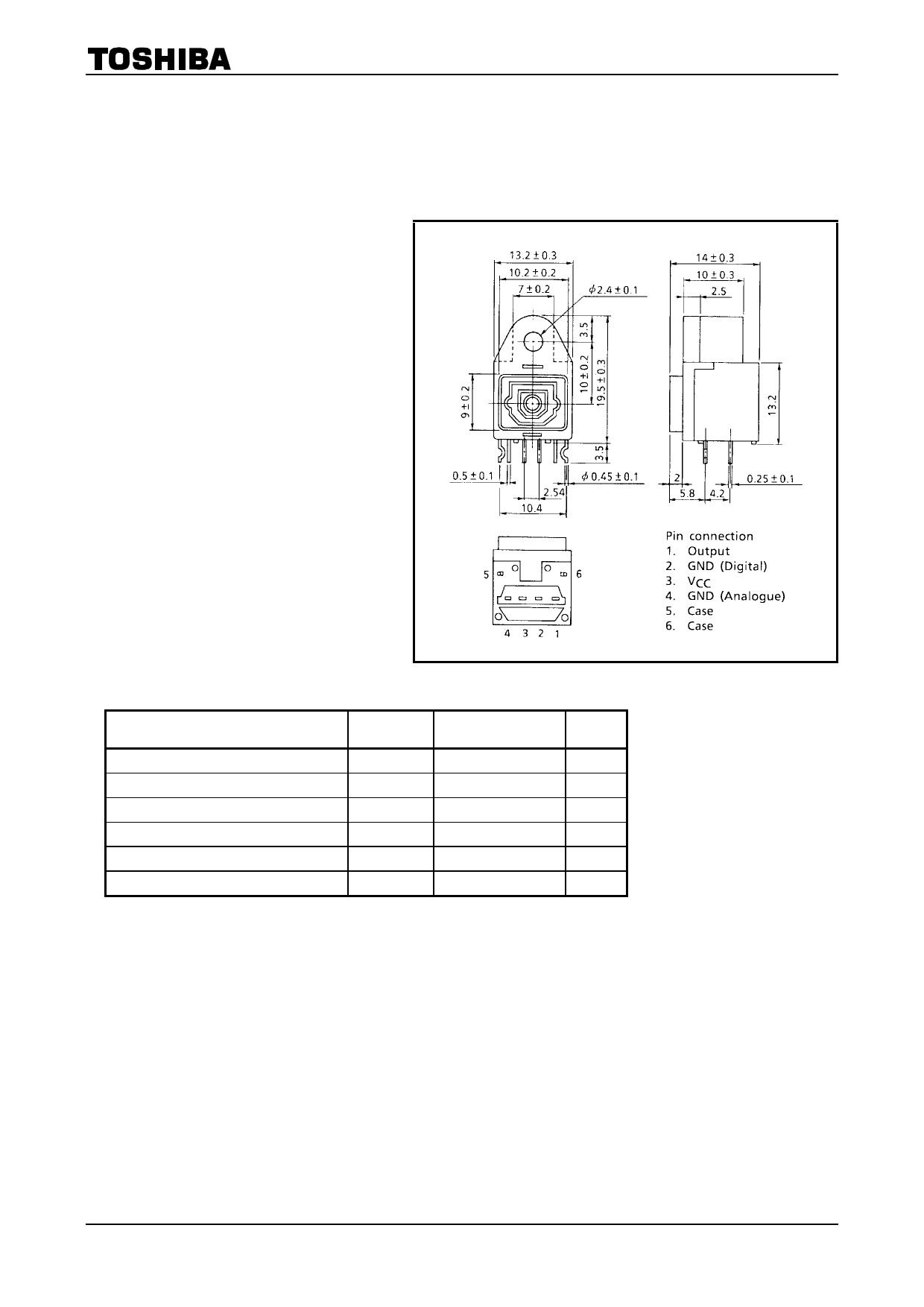
TORX193K
Unit: mm
1. Maximum Ratings (Ta = 25°C)
Characteristics
Symbol
Rating
Storage Temperature
Operating Temperature
Supply Voltage
Low Level Output Current
High Level Output Current
Soldering Temperature
Tstg
Topr
VCC
IOL
IOH
Tsol
−40 to 85
−40 to 85
−0.5 to 7
20
−1
260 (Note 1)
Note 1: Soldering time ≤ 10 s (More than 1 mm apart from the package).
Unit
°C
°C
V
mA
mA
°C
1 2001-08-10
1 page 
5. Application Circuit
TORX193K
6. Precautions during use
(1) Maximum rating
The maximum ratings are the limit values which must not be exceeded when using the device. Any
one of the rating must not be exceeded. If The maximum rating is exceeded, the characteristics may
not be recovered. In some extreme cases, the device may be permanently damage.
(2) Soldering
Optical modules use semiconductor devices internally. However, in principle, optical modules are
optical components. At soldering, take care that flux dose not contact the emitting surface or
detecting surface. Also take care at flux removal after soldering.
Some optical modules come with protective cap. The protective cap is used to avoid malfunction when
the optical module is not in use. Not that it is not dust or waterproof.
As mentioned before, optical modules are optical component. Thus, in principle, soldering where there
may be flux residue or flux removal after soldering is not recommended. Toshiba recommends that
soldering be performed without the optical module mounted on the board. Then, after the board is
cleaned, solder the optical module manually. Do not perform any further cleaning.
If the optical module cannot be soldered manually, use non−halogen (chlorine−free) flux and make
sure, without cleaning, there is no residue such as chlorine. This is one of the ways to eliminate the
effects of flux. In such a case, check the reliability.
(3) Noise resistance
Where the fiber optic receiving module case uses conductive resin, shield by connecting the
reinforcing pin at a front end of the module to GND. When using this optical module, connect the pin
to SIGNAL−GND.
Where the fiber optic receiving module case has a resistance of several tens of ohms, take care that
the case does not contact power line of other circuits.
It is believed that the use of optical transfer devices improve the noise resistance. In principle, optical
fiber is not affected by noise. However, especially receiving module which handle signals whose level
is extremely small, are comparatively more susceptible to noise.
TOSLINK improves noise resistance using a conductive case. However, the current of the signal
output from the photodiode of the optic receiving module is extremely small. Thus, depending on the
usage environment, shielding the case is not sufficient for noise resistance.
When using TOSLINK, Toshiba recommends that you test using the actual device and check the
noise resistance.
Use a simple noise filter on the TOSLINK fiber optic receiving module power line. If the ripple in
power supply used is high, further reinforce the filter.
When locating the optical module in an area susceptible to radiated noise, increase shielding by
covering the optical module and the power line filter using a metallic cover.
(4) Vibration and shock
This module is resin−molded construction with wire fixed by resin. This structure is relatively sound
against vibration or shock, In actual equipment, there are some cases where vibration, shock, and
stress is applied to soldered parts or connected parts, resultingin line cut. Attention must be paid to
the design of the mechanism for applications which are subject to large amounts of vibration.
5 2001-08-10
5 Page | ||
| Páginas | Total 7 Páginas | |
| PDF Descargar | [ Datasheet TORX193K.PDF ] | |
Hoja de datos destacado
| Número de pieza | Descripción | Fabricantes |
| TORX193 | FIBER OPTIC RECEIVING MODULE | Toshiba Semiconductor |
| TORX193K | FIBER OPTIC RECEIVING MODULE | Toshiba Semiconductor |
| Número de pieza | Descripción | Fabricantes |
| SLA6805M | High Voltage 3 phase Motor Driver IC. |
Sanken |
| SDC1742 | 12- and 14-Bit Hybrid Synchro / Resolver-to-Digital Converters. |
Analog Devices |
|
DataSheet.es es una pagina web que funciona como un repositorio de manuales o hoja de datos de muchos de los productos más populares, |
| DataSheet.es | 2020 | Privacy Policy | Contacto | Buscar |