|
|
|
PDF NUF9002FC Data sheet ( Hoja de datos )
| Número de pieza | NUF9002FC | |
| Descripción | Low Capacitance 10 Line EMI Filter | |
| Fabricantes | ON Semiconductor | |
| Logotipo | ||
Hay una vista previa y un enlace de descarga de NUF9002FC (archivo pdf) en la parte inferior de esta página. Total 4 Páginas | ||
|
No Preview Available !
www.DataSheet4U.com
NUF9002FC
Low Capacitance 10 Line
EMI Filter with ESD
Protection
This device is a ten−line EMI filter array for wireless applications.
Greater than −25 dB attenuation is obtained at frequencies from
900 MHz to 3.0 GHz. ESD protection is provided across all
capacitors.
Features
• EMI Filtering and ESD Protection
• Integration of 50 Discretes
• Provides Protection for IEC61000−4−2 (Level 4)
♦ 8.0 kV (Contact)
• Flip−Chip Package
• Moisture Sensitivity Level 1
• ESD Rating: Machine Model = C; Human Body Model = 3B
• Pb−Free Package is Available*
Benefits
• Reduces EMI/RFI Emissions on a Data Line
• Integrated Solution Offers Cost and Space Savings
• Reduces Parasitic Inductances Which Offer a More “Ideal” Low Pass
Filter Response
• Integrated Solution Improves System Reliability
Applications
• LCD for Cell Phones and PDAs
• Computers and Printers
• Communication Systems
• MP3 Players
MAXIMUM RATINGS (TA = 25°C unless otherwise noted)
Rating
Symbol
Value
Unit
ESD Discharge
IEC61000−4−2
Contact Discharge
VPP
8.0 kV
Steady−State Power per Resistor
PR 100 mW
Steady−State Power per Package
PT 200 mW
Operating Temperature Range
TOP −40 to +85 °C
Storage Temperature Range
TSTG −55 to +150 °C
Junction Temperature
TJ
+125
°C
Stresses exceeding Maximum Ratings may damage the device. Maximum
Ratings are stress ratings only. Functional operation above the Recommended
Operating Conditions is not implied. Extended exposure to stresses above the
Recommended Operating Conditions may affect device reliability.
*For additional information on our Pb−Free strategy and soldering details, please
download the ON Semiconductor Soldering and Mounting Techniques
Reference Manual, SOLDERRM/D.
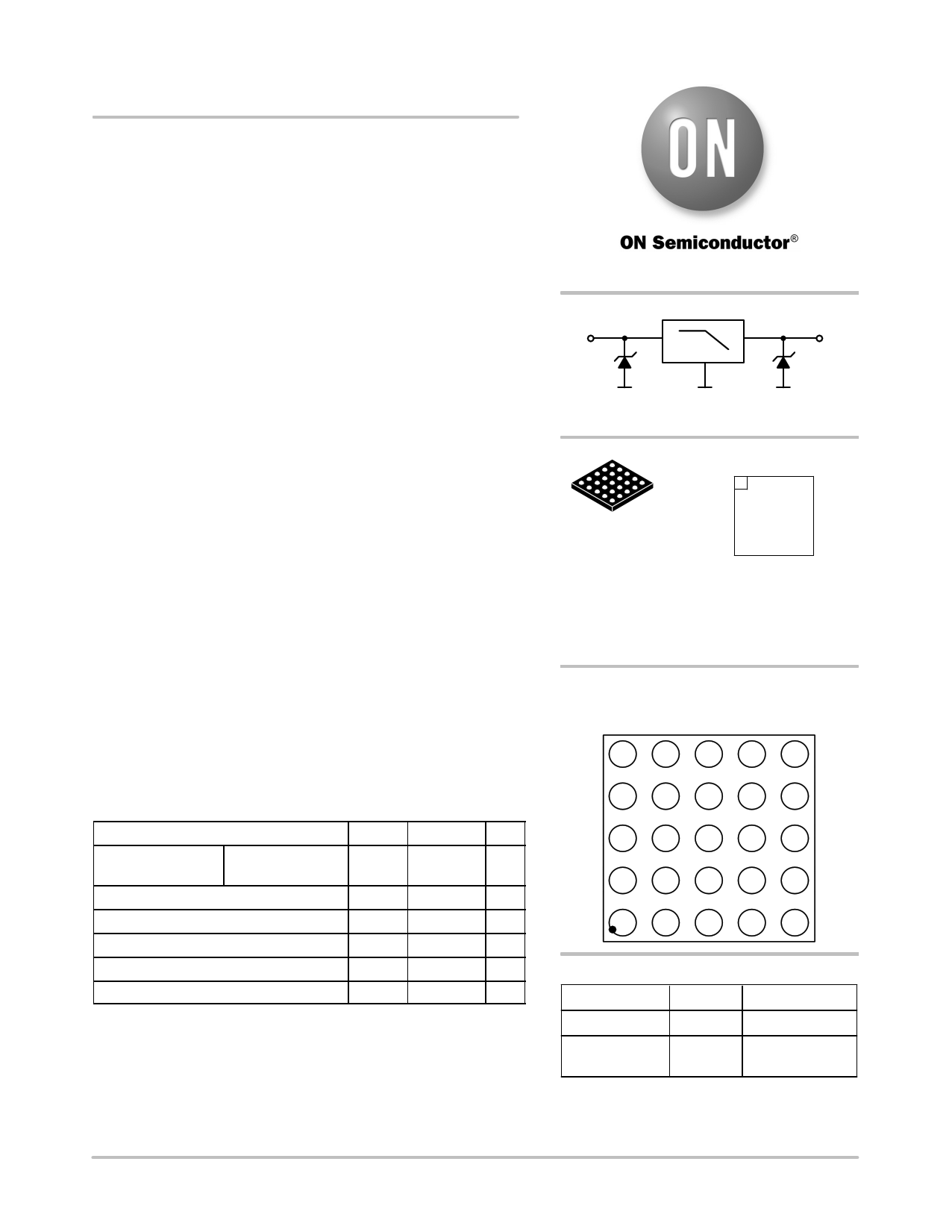
INPUT
http://onsemi.com
LOW−PASS FILTER
OUTPUT
RI/O = 100 W
Cinput = 28 pF
ÇÇÇÇMARKING DIAGRAM
A1 Flip−Chip
NUF9002
AYWWG
CASE 499G
G
NUF9002 = Specific Device Code
A = Assembly Location
Y = Year
WW = Work Week
G = Pb−Free Package
(Note: Microdot may be in either location)
PIN CONFIGURATION
(Ball Side)
1 234 5
E O1 O2 O3 O4 O5
D O6 O7 O8 O9 O10
C GND GND GND GND GND
B IN6 IN7 IN8 IN9 IN10
A IN1 IN2 IN3 IN4 IN5
ORDERING INFORMATION
Device
NUF9002FCT1
Package
Flip−Chip
Shipping†
3000 Tape & Reel
NUF9002FCT1G Flip−Chip 3000 Tape & Reel
(Pb−Free)
†For information on tape and reel specifications,
including part orientation and tape sizes, please
refer to our Tape and Reel Packaging Specifications
Brochure, BRD8011/D.
© Semiconductor Components Industries, LLC, 2006
March, 2006 − Rev. 1
1
Publication Order Number:
NUF9002FC/D
1 page | ||
| Páginas | Total 4 Páginas | |
| PDF Descargar | [ Datasheet NUF9002FC.PDF ] | |
Hoja de datos destacado
| Número de pieza | Descripción | Fabricantes |
| NUF9002FC | Low Capacitance 10 Line EMI Filter | ON Semiconductor |
| Número de pieza | Descripción | Fabricantes |
| SLA6805M | High Voltage 3 phase Motor Driver IC. |
Sanken |
| SDC1742 | 12- and 14-Bit Hybrid Synchro / Resolver-to-Digital Converters. |
Analog Devices |
|
DataSheet.es es una pagina web que funciona como un repositorio de manuales o hoja de datos de muchos de los productos más populares, |
| DataSheet.es | 2020 | Privacy Policy | Contacto | Buscar |