|
|
|
PDF AN103 Data sheet ( Hoja de datos )
| Número de pieza | AN103 | |
| Descripción | The FET Constant-Current Source/Limiter | |
| Fabricantes | Siliconix | |
| Logotipo | ||
Hay una vista previa y un enlace de descarga de AN103 (archivo pdf) en la parte inferior de esta página. Total 5 Páginas | ||
|
No Preview Available !
www.DataSheet4U.com
The FET Constant-Current Source/Limiter
AN103
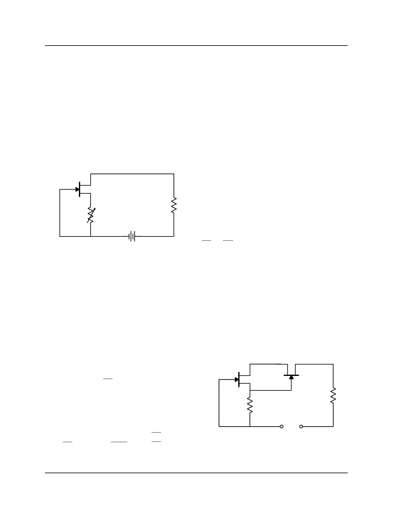
Introduction
The combination of low associated operating voltage and
high output impedance makes the FET attractive as a
constant-current source. An adjustable-current source (Fig-
ure 1) may be built with a FET, a variable resistor, and a
small battery. For optimum thermal stability, the FET should
be biased near the zero temperature coefficient point.
D
S
RS
–+
RL
A change in supply voltage or a change in load imped-
ance, will change ID by only a small factor because of the
low output conductance goss.
DID = (DVDS)(goss)
(3)
The value of goss is an important consideration in the ac-
curacy of a constant-current source where the supply volt-
age may vary. As goss may range from less than 1 mS to
more than 50 mS according to the FET type, the dynamic
impedance can be greater than 1 MW to less than 20 kW.
This corresponds to a current stability range of 1 mA to
50 mA per volt. The value of goss also depends on the op-
erating point. Output conductance goss decrease approxi-
mately linearly with ID. The relationship is
ID
IDSS
+
goss
gȀoss
(4)
Figure 1. Field-Effect Transistor Current Source
NO TAG
where goss = gȀoss
(5)
Whenever the FET is operated in the current saturated re-
gion, its output conductance is very low. This occurs
whenever the drain-source voltage VDS is at least 50%
greater than the cut-off voltage VGS(off). The FET may be
biased to operate as a constant-current source at any cur-
rent below its saturation current IDSS.
Basic Source Biasing
For a given device where IDSS and VGS(off) are known, the
approximate VGS required for a given ID is
ƪ ǒ Ǔ ƫVGS + VGS(off)
1ńk
1–
ID
IDSS
(1)
where k can vary from 1.8 to 2.0, depending on device ge-
ometry. If K = 2.0, the series resistor RS required between
source and gate is
RS
+
VGS
ID
ǒ Ǹ Ǔor
RS
+
VGS(off)
ID
1–
ID
IDSS
(2)
when VGS = 0
(6)
So as VGS → VGS(off), goss → Zero. For best regulation,
ID must be considerably less than IDSS.
Cascading for Low goss
It is possible to achieve much lower goss per unit ID by
cascading two FETs, as shown in Figure 2.
D
Q1
S
SD
Q2
RS
–+
VDD
RL
Figure 2. Cascade FET Current Source
Updates to this app note may be obtained via facsimile by calling Siliconix FaxBack, 1-408-970-5600. Please request FaxBack document #70596.
Siliconix
10-Mar-97
1
1 page 
AN103
Choosing the Correct JFET for Source
Biasing
Each of the Siliconix device data sheets include typical
transfer curves that can be used as illustrated in Figure 7.
Several popular devices are ideal for source biased cur-
rent sources covering a few mAs to 20 mA. To aid the de-
signer, the devices in Table 1 have been plotted to show
the drain current, ID, versus the source resistance, RS, in
Figures 8, 9, and 10. Most plots include the likely worst
case ID variations for a particular RS. For tighter current
control, the JFET production lot can be divided into
ranges with an appropriate resistor selection for each
range.
Table 1: Source Biasing Device Recommendations
Practical
Current
Range ID
(mA)
0.01 – 0.02
0.01 – 0.04
0.02 – 0.1
0.01 – 0.1
0.02 – 0.3
0.1 – 2
0.2 – 10
Through-Hole
Plastic Device
PN4117A
PN4118A
PN4119A
J201
J202
J113
J112
Surface
Mount
Device
SST4117
SST4118
SST4119
SST201
SST202
SST113
SST112
Metal Can
Device
2N4117A
2N4118A
2N4119A
2N4338
2N4339
2N4393
2N4392
20
–55_C
10
125_C
Min 2N4393
1 SST/J113
VDD
Mid
TJ = 25_C
2N4393,
SST/J113 Max
Mid
2N4392,
SST/J112
Min 2N4392,
SST/J112
VDD = 5 to 30 V
TJ = 25_C except as noted
0.1
0.1
RS
0.5 1
RS – Source Resistance (kW)
5
Figure 10. JFET Source Biased Drain-Current vs. Source Resistance
10
Siliconix
10-Mar-97
5
5 Page | ||
| Páginas | Total 5 Páginas | |
| PDF Descargar | [ Datasheet AN103.PDF ] | |
Hoja de datos destacado
| Número de pieza | Descripción | Fabricantes |
| AN100 | An Overview if Data Converters | Philips |
| AN1001 | The Next Step in Surface-Mount Power MOSFETs | Vishay Siliconix |
| AN1003 | Thyristors | Littelfuse |
| AN1007 | Switcher Replaces MAG Amps in Silver Boxes | ST Microelectronics |
| Número de pieza | Descripción | Fabricantes |
| SLA6805M | High Voltage 3 phase Motor Driver IC. |
Sanken |
| SDC1742 | 12- and 14-Bit Hybrid Synchro / Resolver-to-Digital Converters. |
Analog Devices |
|
DataSheet.es es una pagina web que funciona como un repositorio de manuales o hoja de datos de muchos de los productos más populares, |
| DataSheet.es | 2020 | Privacy Policy | Contacto | Buscar |