|
|
|
PDF MSWT-4-20 Data sheet ( Hoja de datos )
| Número de pieza | MSWT-4-20 | |
| Descripción | Low Video Leakage | |
| Fabricantes | Mini-Circuits | |
| Logotipo | ||
Hay una vista previa y un enlace de descarga de MSWT-4-20 (archivo pdf) en la parte inferior de esta página. Total 2 Páginas | ||
|
No Preview Available !
www.DataSheet4U.com
SwitchSurface Mount
50Ω Transfer, DC to 2.0 GHz Low Video Leakage
MSWT-4-20+
MSWT-4-20
Maximum Ratings
Operating Temperature
Storage Temperature
-40°C to 85°C
-55°C to 100°C
Pin Connections
Tx
Rx
J1
J2
CONTROL 1
CONTROL 2
CONTROL 3
CONTROL 4
Outline Drawing
2
6
4
8
1
3
5
7
Features
• wideband, DC to 2.0 GHz
• low video leakage, 15 mVp-p typ.
• excellent VSWR, 1.2:1 typ.
Applications
• transmitter/receiver
• automatic test equipment
CASE STYLE: XX211
PRICE: $3.45 ea. QTY (10)
+ RoHS compliant in accordance
with EU Directive (2002/95/EC)
The +suffix identifies RoHS Compliance. See our web site
for RoHS compliance methodologies and qualifications.
Electrical Specifications
FREQ.
(GHz)
fL fU
DC 2.0
Path
Tx-J1/J2
J1/J2-Rx
Tx-Rx
INSERTION LOSS
(dB)
DC-100
MHz
100-500
MHz
500-1000
MHz
Typ. Max. Typ. Max. Typ. Max.
0.9 1.2 1.1 1.5 1.25 1.8
1.1 1.4 1.3 1.7 1.5 2.0
——————
1dB COMPR.
(dBm)
1000-2000 DC-100 100-500 500-1000 1000-2000 DC-100
MHz MHz MHz MHz MHz
MHz
Typ. Max. Typ. Typ. Typ.
1.45 2.2 18 25 28
Typ Typ. Min.
29 51 44
1.6 2.2 16 18 20
—— — — —
22 52 46
— 60 53
ISOLATION
(dB)
100-500
MHz
500-1000 1000-2000
MHz MHz
Typ. Min. Typ. Min. Typ. Min
34 27 26 21 19 15
37 31 29 24 21 17
41 36 34 27 28 21
Outline Dimensions
(
)inch
mm
ABCDE F
.163 .210 .077 .250 .220 .050
4.14 5.33 1.96 6.35 5.59 1.27
G
.017
0.43
H J K M N P wt
.009 .025 .030 .050 .030 .270 grams
0.23 0.64 0.76 1.27 0.76 6.86 0.10
Demo Board MCL P/N: TB-202
Suggested PCB Layout (PL-220)
Additional Specifications
Control Voltage
Control Current, mA
-8/0 for compression spec, -8 to -5/0 for all other specs
0.2 max to -8V, 0.02 max at 0 to -0.2V
VSWR(:1)
Rise/Fall time (10%-90%), ns
Switching time, 50% of Control to
90% RF(Turn-on), ns
10% RF(Turn-off), ns
**Video Leakage, mVp-p
0/-5V Control
DC-.1GHz
1.2 typ.
1.65 max.
.1-.5GHz
1.25 typ.
1.8 max.
.5-1GHz
1.4 typ.
1.9 max.
2 typ.
4 typ
4 typ
15 typ.
1-2GHz
1.4 typ.
1.7 max.
Control Ports
1 234
0 -v -v -v
-v 0 -v -v
-v -v 0 -v
-v -v -v 0
0 -v 0 -v
-v 0 -v 0
"On" Path
(other paths are "OFF")
TX-J2
TX-J1
RX-J1
RX-J2
TX-J2 & RX-J1
TX-J1 & RX-J2
** Video leakage or break through is defined as leakage of switching signal to RF output ports.
1. RF Power Input (dBm), Max.
DC-100MHz
100-500 MHz
500-2000MHz
• Steady State Control 0/-8V
24
27 33
• As a Modulator
12 17 23
2. Control Current, 500µA (occurs at -9V to -12V typ.)
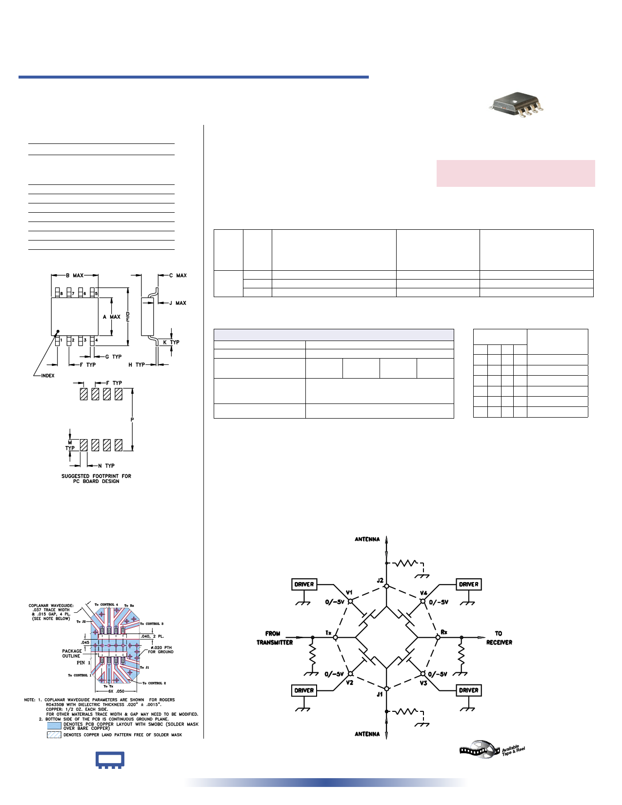
Application Note for MSWT-4-20 Transmit-Receive Switch:
The functional schematic diagram for a diversity application of the switch is shown in Figure 1, with the required external components including 4
independent drivers at the control ports. When operation as a transfer switch is desired only 2 drivers are needed, one connected to the V1 and V3 ports
together, and the other connected to the V2 and V4 ports. In either case, two DC return paths are needed for the control voltages, represented by the
ground symbols in the diagram. These returns must be via oppositely situated RF ports (Tx and Rx or J1 and J2), and can be furnished incidentally by the
user's RF terminating devices themselves. However, if those devices are AC-coupled (that is, they contain DC blocking capacitors), then the shunt resis-
tors shown in the diagram are needed. The resistor should be installed either at the Tx and Rx ports (connection shown as solid), or at J1 and J2 (shown
dotted), with equal effect. If one external RF device has a DC return to ground, for example, then only one resistor is needed; it must be installed at the
opposite RF port of the switch. The resistance of each of the external DC returns should be 20K ohms or less, for proper ON/OFF FETs.
Mini-Circuits® INTERNET http://www.minicircuits.com
P.O. Box 350166, Brooklyn, New York 11235-0003 (718) 934-4500 Fax (718) 332-4661
Distribution Centers NORTH AMERICA 800-654-7949 • 417-335-5935 • Fax 417-335-5945 • EUROPE 44-1252-832600 • Fax 44-1252-837010
Mini-Circuits ISO 9001 & ISO 14001 Certified
REV. B
M102713
MSWT-4-20
WP/CP
060117
Page 1 of 2
1 page | ||
| Páginas | Total 2 Páginas | |
| PDF Descargar | [ Datasheet MSWT-4-20.PDF ] | |
Hoja de datos destacado
| Número de pieza | Descripción | Fabricantes |
| MSWT-4-20 | Low Video Leakage | Mini-Circuits |
| Número de pieza | Descripción | Fabricantes |
| SLA6805M | High Voltage 3 phase Motor Driver IC. |
Sanken |
| SDC1742 | 12- and 14-Bit Hybrid Synchro / Resolver-to-Digital Converters. |
Analog Devices |
|
DataSheet.es es una pagina web que funciona como un repositorio de manuales o hoja de datos de muchos de los productos más populares, |
| DataSheet.es | 2020 | Privacy Policy | Contacto | Buscar |