|
|
|
PDF CS4351 Data sheet ( Hoja de datos )
| Número de pieza | CS4351 | |
| Descripción | 192 kHz Stereo DAC | |
| Fabricantes | Cirrus Logic | |
| Logotipo | ||
Hay una vista previa y un enlace de descarga de CS4351 (archivo pdf) en la parte inferior de esta página. Total 30 Páginas | ||
|
No Preview Available !
CS4351
192 kHz Stereo DAC with 2 Vrms Line Out
Features
! Multi-Bit Delta-Sigma Modulator
! 24-Bit Conversion
! Up to 192 kHz Sample Rates
! 112 dB Dynamic Range
! -100 dB THD+N
! +3.3 V, +9 to 12 V, and VL Power Supplies
! 2 Vrms Output into 5 kΩ AC Load
! Digital Volume Control with Soft Ramp
– 119 dB Attenuation
– 1/2 dB Step Size
– Zero Crossing Click-Free Transitions
! ATAPI Mixing
! Low Clock Jitter Sensitivity
! Popguard® Technology for Control of Clicks
and Pops
Description
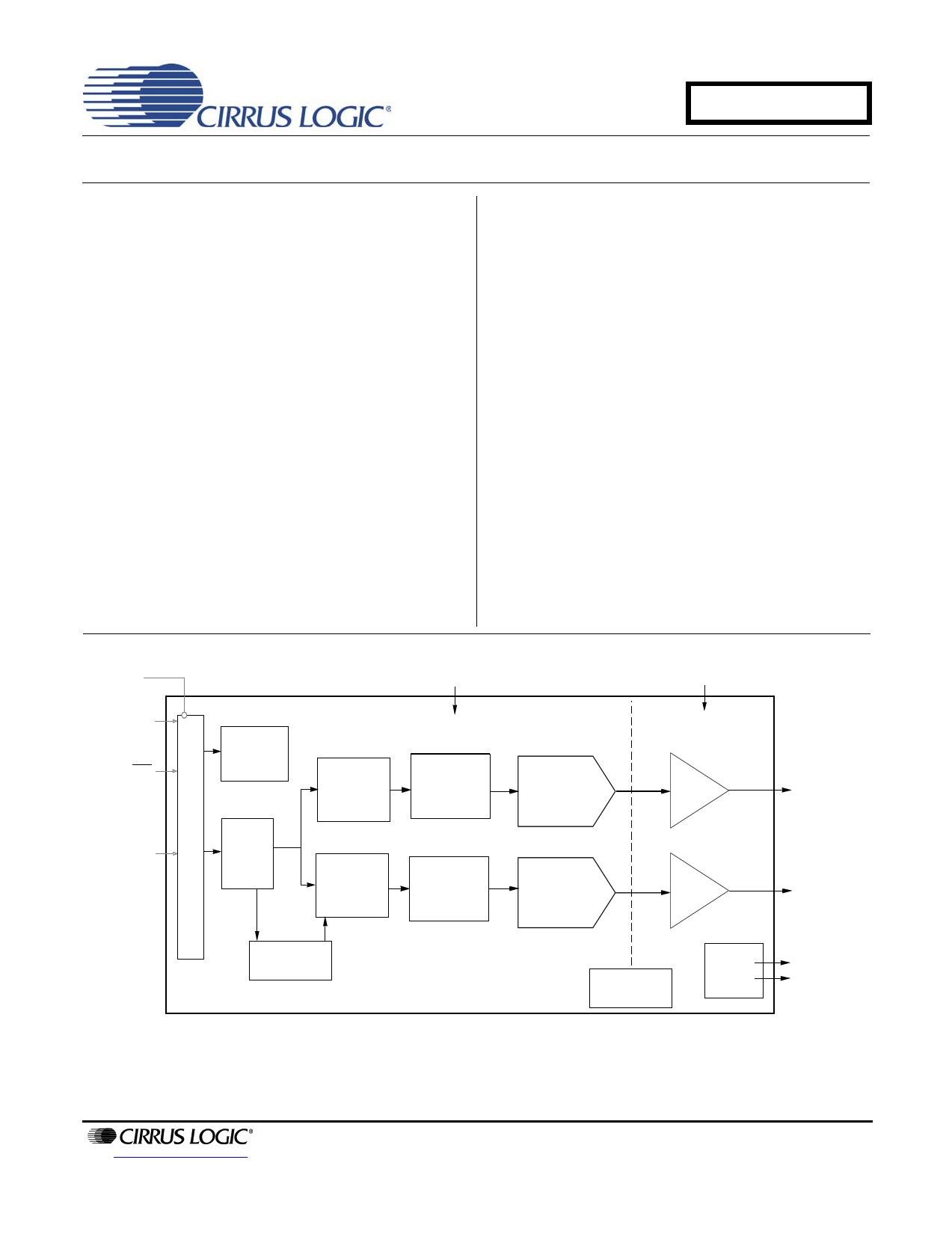
The CS4351 is a complete stereo digital-to-analog sys-
tem including digital interpolation, fifth-order multi-bit
delta-sigma digital-to-analog conversion, digital de-em-
phasis, volume control, channel mixing, analog filtering,
and on-chip 2 Vrms line-level driver. The advantages of
this architecture include ideal differential linearity, no
distortion mechanisms due to resistor matching errors,
no linearity drift over time and temperature, high toler-
ance to clock jitter, and a minimal set of external
components.
The CS4351 is available in a 20-pin TSSOP package in
both Commercial (-10°C - +70°C) and Automotive
grades (-40°C to +85°C). The CDB4351 Customer
Demonstration board is also available for device evalu-
ation and implementation suggestions. Please see
“Ordering Information” on page 37 for complete details.
These features are ideal for cost-sensitive, 2-channel
audio systems including DVD players, A/V receivers,
set-top boxes, digital TVs and VCRs, mini-component
systems, and mixing consoles.
8 Vto 3.3V
dwareor I2C/SPI
Control Data
Reset
erial Audio Input
3.3 V
Register/Hardware
Configuration
PCM
Serial
Interface
Interpolation
Filter with
Volume Control
Interpolation
Filter with
Volume Control
Multibit
∆Σ Modulator
Multibit
∆Σ Modulator
Auto Speed Mode
Detect
9 Vto 12 V
DAC
Amp 2 Vrms LineLevel
+
Filter
Left Channel Outpu
DAC
Amp 2 Vrms LineLevel
+ Right Channel
Filter Output
Internal Voltage
Reference
External
Mute
Control
Left and Right
Mute Controls
http://www.cirrus.com
Copyright © Cirrus Logic, Inc. 2005
(All Rights Reserved)
DECEMBER '05
DS566F1
1 page 
1. PIN DESCRIPTION
SDIN
SCLK
LRCK
MCLK
VD
GND
DIF1(SCL/CCLK)
DIF0(SDA/CDIN)
DEM(AD0/CS)
RST
1
2
3
4
5
6
7
8
9
10
20 VL
19 AMUTEC
18 AOUTA
17 VA_H
16 GND
15 AOUTB
14 BMUTEC
13 VQ
12 VBIAS
11 VA
CS4351
Pin Name #
Pin Description
SDIN
1 Serial Audio Data Input (Input) - Input for two’s complement serial audio data.
SCLK
2 Serial Clock (Input) - Serial clock for the serial audio interface.
LRCK
3
Left / Right Clock (Input) - Determines which channel, Left or Right, is currently active on the serial
audio data line.
MCLK
4 Master Clock (Input) - Clock source for the delta-sigma modulator and digital filters.
VD 5 Digital Power (Input) - Positive power supply for the digital section.
GND
6
16
Ground (Input) - Ground reference.
RST
10 Reset (Input) - Powers down device and resets all internal resisters to their default settings when
enabled.
VA 11 Low Voltage Analog Power (Input) - Positive power supply for the analog section.
VBIAS
12 Positive Voltage Reference (Output) - Positive reference voltage for the internal DAC.
VQ 13 Quiescent Voltage (Output) - Filter connection for internal quiescent voltage.
VA_H
17 High Voltage Analog Power (Input) - Positive power supply for the analog section.
VL 20 Serial Audio Interface Power (Input) - Positive power for the serial audio interface
BMUTEC
AMUTEC
14
19 Mute Control (Output) - Control signal for optional mute circuit.
AOUTB
AOUTA
15 Analog Outputs (Output) - The full scale analog line output level is specified in the Analog Character-
18 istics table.
Control Port Definitions
SCL/CCLK
7 Serial Control Port Clock (Input) - Serial clock for the control port interface.
SDA/CDIN
8 Serial Control Data (Input/Output) - Input/Output for I²C data. Input for SPI data.
AD0/CS
9 Address Bit 0 / Chip Select (Input) - Chip address bit in I²C Mode. Control Port enable in SPI Mode.
Stand-Alone Definitions
DIF0
DIF1
8 Digital Interface Format (Input) - Defines the required relationship between the Left Right Clock,
7 Serial Clock, and Serial Audio Data.
DEM
9
De-emphasis (Input) - Selects the standard 15 µs/50 µs digital de-emphasis filter response for 44.1
kHz sample rates
DS566F1
5
5 Page 
Switching Characteristics - Control Port - I²C® Format
(Inputs: Logic 0 = GND, Logic 1 = VL, CL = 20 pF)
Parameter
SCL Clock Frequency
RST Rising Edge to Start
Bus Free Time Between Transmissions
Start Condition Hold Time (prior to first clock pulse)
Clock Low time
Clock High Time
Setup Time for Repeated Start Condition
SDA Hold Time from SCL Falling
SDA Setup time to SCL Rising
Rise Time of SCL and SDA
Fall Time SCL and SDA
Setup Time for Stop Condition
Acknowledge Delay from SCL Falling
(Note 7)
Symbol
fscl
tirs
tbuf
thdst
tlow
thigh
tsust
thdd
tsud
trc, trc
tfc, tfc
tsusp
tack
Min
-
500
4.7
4.0
4.7
4.0
4.7
0
250
-
-
4.7
300
Notes:
7. Data must be held for sufficient time to bridge the transition time, tfc, of SCL.
CS4351
Max
100
-
-
-
-
-
-
-
-
1
300
-
1000
Unit
kHz
ns
µs
µs
µs
µs
µs
µs
ns
µs
ns
µs
ns
RST
t irs
Stop
Start
SDA
t buf
t hdst
t high
Repeated
S ta rt t rd
t hdst
Stop
t fd
t fc t susp
SCL
t
low
t
hdd
t sud t ack
t sust
t rc
Figure 2. Control Port Timing - I²C Format
DS566F1
11
11 Page | ||
| Páginas | Total 30 Páginas | |
| PDF Descargar | [ Datasheet CS4351.PDF ] | |
Hoja de datos destacado
| Número de pieza | Descripción | Fabricantes |
| CS4350 | 192 kHz Stereo DAC | Cirrus Logic |
| CS4351 | 192 kHz Stereo DAC | Cirrus Logic |
| CS4352 | 192 kHz Stereo DAC | Cirrus Logic |
| CS4353 | 3.3 V Stereo Audio DAC | Cirrus Logic |
| Número de pieza | Descripción | Fabricantes |
| SLA6805M | High Voltage 3 phase Motor Driver IC. |
Sanken |
| SDC1742 | 12- and 14-Bit Hybrid Synchro / Resolver-to-Digital Converters. |
Analog Devices |
|
DataSheet.es es una pagina web que funciona como un repositorio de manuales o hoja de datos de muchos de los productos más populares, |
| DataSheet.es | 2020 | Privacy Policy | Contacto | Buscar |