|
|
|
PDF DAC8801 Data sheet ( Hoja de datos )
| Número de pieza | DAC8801 | |
| Descripción | Serial Input Multiplying Digital-to-Analog Converter | |
| Fabricantes | Burr-Brown | |
| Logotipo | ||
Hay una vista previa y un enlace de descarga de DAC8801 (archivo pdf) en la parte inferior de esta página. Total 16 Páginas | ||
|
No Preview Available !
www.DataSheet4U.com
BurrĆBrown Products
from Texas Instruments
DAC8801
SLAS403A – NOVEMBER 2004 – REVISED DECEMBER 2004
14-Bit, Serial Input Multiplying Digital-to-Analog Converter
FEATURES
• 14-Bit Monotonic
• ±1 LSB INL
• ±0.5 LSB DNL
• Low Noise: 12 nV/√Hz
• Low Power: IDD = 2 µA
• +2.7 V to +5.5 V Analog Power Supply
• 2 mA Full-Scale Current ±20%
with VREF = 10 V
• 0.5 µs Settling Time
• 4-Quadrant Multiplying Reference-Input
• Reference Bandwidth: 10 MHz
• ±10 V Reference Input
• Reference Dynamics: -105 THD
• 3-Wire 50-MHz Serial Interface
• Tiny 8-Lead 3 x 3 mm SON and 3 x 5 mm
MSOP Packages
• Industry-Standard Pin Configuration
APPLICATIONS
• Automatic Test Equipment
• Instrumentation
• Digitally Controlled Calibration
• Industrial Control PLCs
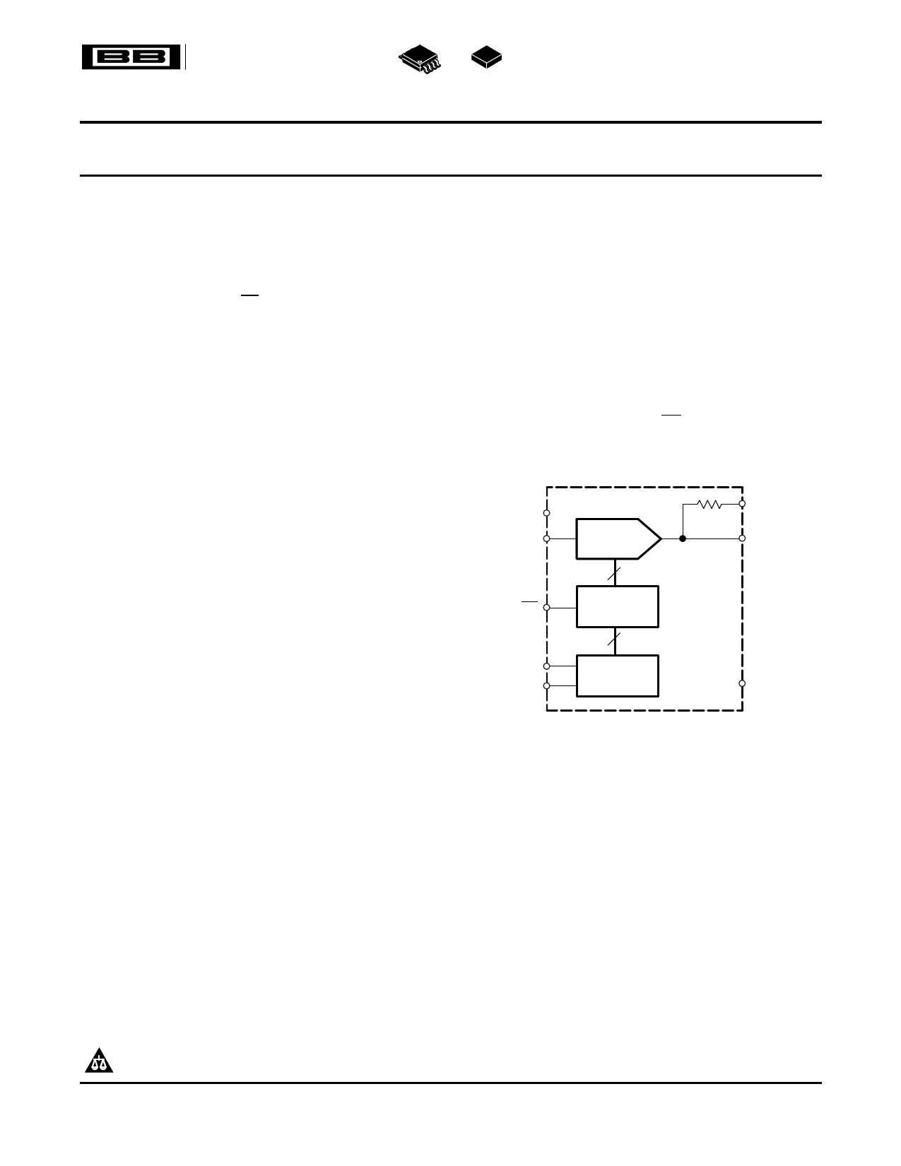
DESCRIPTION
The DAC8801 multiplying digital-to-analog converter
is designed to operate from a single 2.7-V to 5.5-V
supply.
The applied external reference input voltage VREF
determines the full-scale output current. An internal
feedback resistor (RFB) provides temperature tracking
for the full-scale output when combined with an
external I-to-V precision amplifier.
A serial-data interface offers high-speed, three-wire
microcontroller compatible inputs using data-in (SDI),
clock (CLK), and chip select (CS).
The DAC8801 is packaged in space-saving 8-lead
SON and MSOP packages.
VDD
VREF
CS
CLK
SDI
DAC8801
D/A
Converter
14
DAC
Register
14
Shift
Register
RFB
IOUT
GND
Please be aware that an important notice concerning availability, standard warranty, and use in critical applications of Texas
Instruments semiconductor products and disclaimers thereto appears at the end of this data sheet.
PRODUCTION DATA information is current as of publication date.
Products conform to specifications per the terms of the Texas
Instruments standard warranty. Production processing does not
necessarily include testing of all parameters.
Copyright © 2004, Texas Instruments Incorporated
1 page 
DAC8801
www.ti.com
SLAS403A – NOVEMBER 2004 – REVISED DECEMBER 2004
TYPICAL CHARACTERISTICS: VDD = +5 V
At TA = +25°C, +VDD = +5 V, unless otherwise noted.
LINEARITY ERROR
vs DIGITAL INPUT CODE
1.0
0.8 TA = +25_ C
0.6
0.4
0.2
0
−0.2
−0.4
−0.6
−0.8
−1.0
0
2048 4096 6144 8192 10240 12288 14336 16384
Digital Input Code
Figure 1.
DIFFERENTIAL LINEARITY ERROR
vs DIGITAL INPUT CODE
1.0
0.8 TA = +25_ C
0.6
0.4
0.2
0
−0.2
−0.4
−0.6
−0.8
−1.0
0
2048 4096 6144 8192 10240 12288 14336 16384
Digital Input Code
Figure 2.
LINEARITY ERROR
vs DIGITAL INPUT CODE
1.0
0.8 TA = −40_C
0.6
0.4
0.2
0
−0.2
−0.4
−0.6
−0.8
−1.0
0
2048 4096 6144 8192 10240 12288 14336 16384
Digital Input Code
Figure 3.
DIFFERENTIAL LINEARITY ERROR
vs DIGITAL INPUT CODE
1.0
0.8 TA = −40_C
0.6
0.4
0.2
0
−0.2
−0.4
−0.6
−0.8
−1.0
0
2048 4096 6144 8192 10240 12288 14336 16384
Digital Input Code
Figure 4.
LINEARITY ERROR
vs DIGITAL INPUT CODE
1.0
0.8 TA = +85_ C
0.6
0.4
0.2
0
−0.2
−0.4
−0.6
−0.8
−1.0
0
2048 4096 6144 8192 10240 12288 14336 16384
Digital Input Code
Figure 5.
DIFFERENTIAL LINEARITY ERROR
vs DIGITAL INPUT CODE
1.0
0.8 TA = +85_ C
0.6
0.4
0.2
0
−0.2
−0.4
−0.6
−0.8
−1.0
0
2048 4096 6144 8192 10240 12288 14336 16384
Digital Input Code
Figure 6.
5
5 Page 
DAC8801
www.ti.com
SLAS403A – NOVEMBER 2004 – REVISED DECEMBER 2004
Bipolar Output Circuit
The DAC8801, as a 2-quadrant multiplying DAC, can be used to generate a unipolar output. The polarity of the
full-scale output IOUT is the inverse of the input reference voltage at VREF.
Some applications require full 4-quadrant multiplying capabilities or bipolar output swing. As shown in Figure 22,
external op amp U4 is added as a summing amp and has a gain of 2X that widens the output span to 5 V. A
4-quadrant multiplying circuit is implemented by using a 2.5-V offset of the reference voltage to bias U4.
According to the circuit transfer equation given in Equation 2, input data (D) from code 0 to full scale produces
output voltages of VOUT = -2.5 V to VOUT = +2.5 V.
ǒ ǓVOUT +
D
16, 384
*
1
VREF
(2)
10 kW
10 kW
+2.5 V
(+10 V)
VDD
VDD
RFB
VREF DAC8801
GND
5 kW
C2
−
C1
+
U4
VOUT
OPA277
−
IOUT
+ U2
OPA277
−2.5 V 3 VOUT 3 +2.5 V
(−10 V 3 VOUT 3 +10 V)
Figure 22. Bipolar Output Circuit
Programmable Current Source Circuit
A DAC8801 can be integrated into the circuit in Figure 23 to implement an improved Howland current pump for
precise voltage to current conversions. Bidirectional current flow and high voltage compliance are two features of
the circuit. A application of this circuit includes a 4-mA to 20-mA current transmitter with up to a 500-Ω load. With
a matched resistor network, the load current of the circuit is shown in Equation 3:
(R2 ) R3) ń R1
IL +
R3
VREF D
(3)
R24
15 kW
C1
10 pF
VREF
VDD
VDD RFB
VREF
U1
DAC8801
GND
U2
OPA277
IOUT
−
+
R14
150 kW
R1
150 kW
U2
OPA277
−
+
R2
15 kW
R34
50 W
VOUT
R3
50 W
IL
LOAD
Figure 23. Programmable Bidirectional Current Source Circuit
11
11 Page | ||
| Páginas | Total 16 Páginas | |
| PDF Descargar | [ Datasheet DAC8801.PDF ] | |
Hoja de datos destacado
| Número de pieza | Descripción | Fabricantes |
| DAC8800 | Octal 8-Bit CMOS D/A Converter | Analog Devices |
| DAC8800BR | Octal 8-Bit CMOS D/A Converter | Analog Devices |
| DAC8800FP | Octal 8-Bit CMOS D/A Converter | Analog Devices |
| DAC8800FR | Octal 8-Bit CMOS D/A Converter | Analog Devices |
| Número de pieza | Descripción | Fabricantes |
| SLA6805M | High Voltage 3 phase Motor Driver IC. |
Sanken |
| SDC1742 | 12- and 14-Bit Hybrid Synchro / Resolver-to-Digital Converters. |
Analog Devices |
|
DataSheet.es es una pagina web que funciona como un repositorio de manuales o hoja de datos de muchos de los productos más populares, |
| DataSheet.es | 2020 | Privacy Policy | Contacto | Buscar |