|
|
|
PDF TLP701 Data sheet ( Hoja de datos )
| Número de pieza | TLP701 | |
| Descripción | Industrial inverters Inverter | |
| Fabricantes | Toshiba Semiconductor | |
| Logotipo | ||
Hay una vista previa y un enlace de descarga de TLP701 (archivo pdf) en la parte inferior de esta página. Total 8 Páginas | ||
|
No Preview Available !
www.DataSheet4U.com
TLP701
TOSHIBA Photocoupler GaAℓAs IRED + Photo IC
TLP701
Industrial inverters
Inverter for air conditioners
IGBT/Power MOS FET gate drive
TLP701 consists of a GaAℓAs light-emitting diode and an integrated
photodetector.
This unit is 6-lead SDIP package. The TLP701 is 50% smaller than the 8-pin
DIP and meets the reinforced insulation class requirements of international safety
standards. Therefore the mounting area can be reduced in equipment requiring
safety standard certification.
The TLP701 is suitable for gate driving circuits for IGBTs or power MOSFETs.
In particular, the TLP701 is capable of “direct” gate driving of low-power IGBTs.
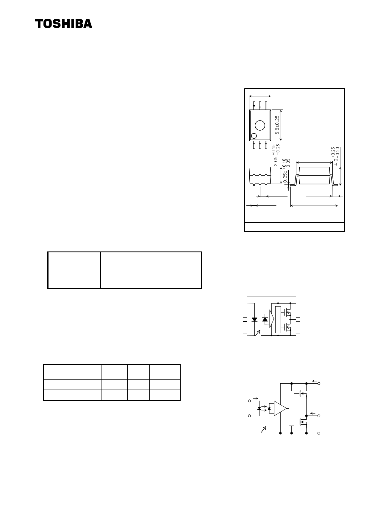
4.58±0.25
654
123
Unit in mm
7.62±0.25
• Peak output current
: ±0.6 A (max)
• Guaranteed performance over temperature : −40 to 100°C
• Supply current
: 2 mA (max)
• Power supply voltage
: 10 to 30 V
• Threshold input current
: IFLH = 5 mA (max)
• Switching time (tpLH / tpHL)
: 700 ns (max)
• Common mode transient immunity
: ±10 kV/µs (min)
• Isolation voltage
: 5000 Vrms (min)
• Construction mechanical rating
7.62-mm pitch
standard type
10.16-mm pitch
TLPXXXF type
Creepage Distance
Clearance
Insulation Thickness
7.0 mm (min)
7.0 mm (min)
0.4 mm (min)
8.0 mm (min)
8.0 mm (min)
0.4 mm (min)
• UL Recognized
: UL1577, File No. E67349
• Option (D4)
TÜV approved
: EN60747-5-2
Certificate No. R50033433
Maximum operating insulation voltage : 890 Vpk
Highest permissible over voltage
: 8000 Vpk
( Note ) When a EN60747-5-2 approved type is needed,
please designate the “Option(D4)”
Truth Table
Input LED Tr1 Tr2 Output
H
ON ON OFF
H
L
OFF
OFF
ON
L
1.27±0.2
0.4±0.1
1.25±0.25
9.7±0.3
TOSHIBA
11-5J1
Weight 0.26 g (t yp .)
11-5J1
Pin Configuration (Top View)
1
2
3 SHIELD
6 1: ANODE
2: NC
3: CATHODE
5 4: GND
5: VO ( OUTPUT )
4 6: VCC
Schematic
IF
1+
VF
3−
(Tr1)
ICC 6
VCC
IO 5
(Tr2)
VO
SHIELD
4
GND
A 0.1-µF bypass capacitor must be connected
between pins 6 and 4. (See Note 6.)
1 2006-01-17
1 page 
Test Circuit 7: tpLH, tpHL, tr, tf, PDD
1
IF
3
6
VO
Rg = 47 Ω
Cg = 3 nF
4
VCC
IF
VO
tr
tpLH
TLP701
tf
tpHL
VOH
90%
50
10%
VOL
Test Circuit 8: CMH, CML
IF 1
SW
AB
3
6
0.1µF
VO
VCM
+−
4
VCC
VCM
VO
90%
10%
tr
• SW A: IF = 5 mA
1V
• SW B: IF = 0 mA
CML =
800 V
tr (µs)
CMH = −
800 V
tf (µs)
1000 V
tf
CMH
26V
CML
CML (CMH) is the maximum rate of rise (fall) of the common mode voltage that can be sustained with the output
voltage in the LOW (HIGH) state.
5 2006-01-17
5 Page | ||
| Páginas | Total 8 Páginas | |
| PDF Descargar | [ Datasheet TLP701.PDF ] | |
Hoja de datos destacado
| Número de pieza | Descripción | Fabricantes |
| TLP700 | GaAAs IRED + Photo IC | Toshiba Semiconductor |
| TLP700F | GaAAs IRED + Photo IC | Toshiba Semiconductor |
| TLP701 | Industrial inverters Inverter | Toshiba Semiconductor |
| TLP701A | Photocouplers | Toshiba Semiconductor |
| Número de pieza | Descripción | Fabricantes |
| SLA6805M | High Voltage 3 phase Motor Driver IC. |
Sanken |
| SDC1742 | 12- and 14-Bit Hybrid Synchro / Resolver-to-Digital Converters. |
Analog Devices |
|
DataSheet.es es una pagina web que funciona como un repositorio de manuales o hoja de datos de muchos de los productos más populares, |
| DataSheet.es | 2020 | Privacy Policy | Contacto | Buscar |