|
|
|
PDF CS51031 Data sheet ( Hoja de datos )
| Número de pieza | CS51031 | |
| Descripción | Fast P-Ch FET Buck Controller | |
| Fabricantes | ON Semiconductor | |
| Logotipo | ||
Hay una vista previa y un enlace de descarga de CS51031 (archivo pdf) en la parte inferior de esta página. Total 10 Páginas | ||
|
No Preview Available !
www.DataSheet4U.com
CS51031
Fast P−Ch FET
Buck Controller
The CS51031 is a switching controller for use in DC−DC
converters. It can be used in the buck topology with a minimum
number of external components. The CS51031 consists of a VCC
monitor for controlling the state of the device, 1.0 A power driver for
controlling the gate of a discrete P−Channel transistor, fixed frequency
oscillator, short circuit protection timer, programmable Soft−Start,
precision reference, fast output voltage monitoring comparator, and
output stage driver logic with latch.
The high frequency oscillator allows the use of small inductors and
output capacitors, minimizing PC board area and systems cost. The
programmable Soft−Start reduces current surges at startup. The short
circuit protection timer significantly reduces the duty cycle to
approximately 1/30 of its cycle during short circuit conditions.
Features
• 1.0 A Totem Pole Output Driver
• High Speed Oscillator (700 kHz max)
• No Stability Compensation Required
• Lossless Short Circuit Protection
• VCC Monitor
• 2.0% Precision Reference
• Programmable Soft−Start
• Wide Ambient Temperature Range:
♦ Industrial Grade: −40°C to 85°C
♦ Commercial Grade: 0°C to 70°C
• Pb−Free Packages are Available
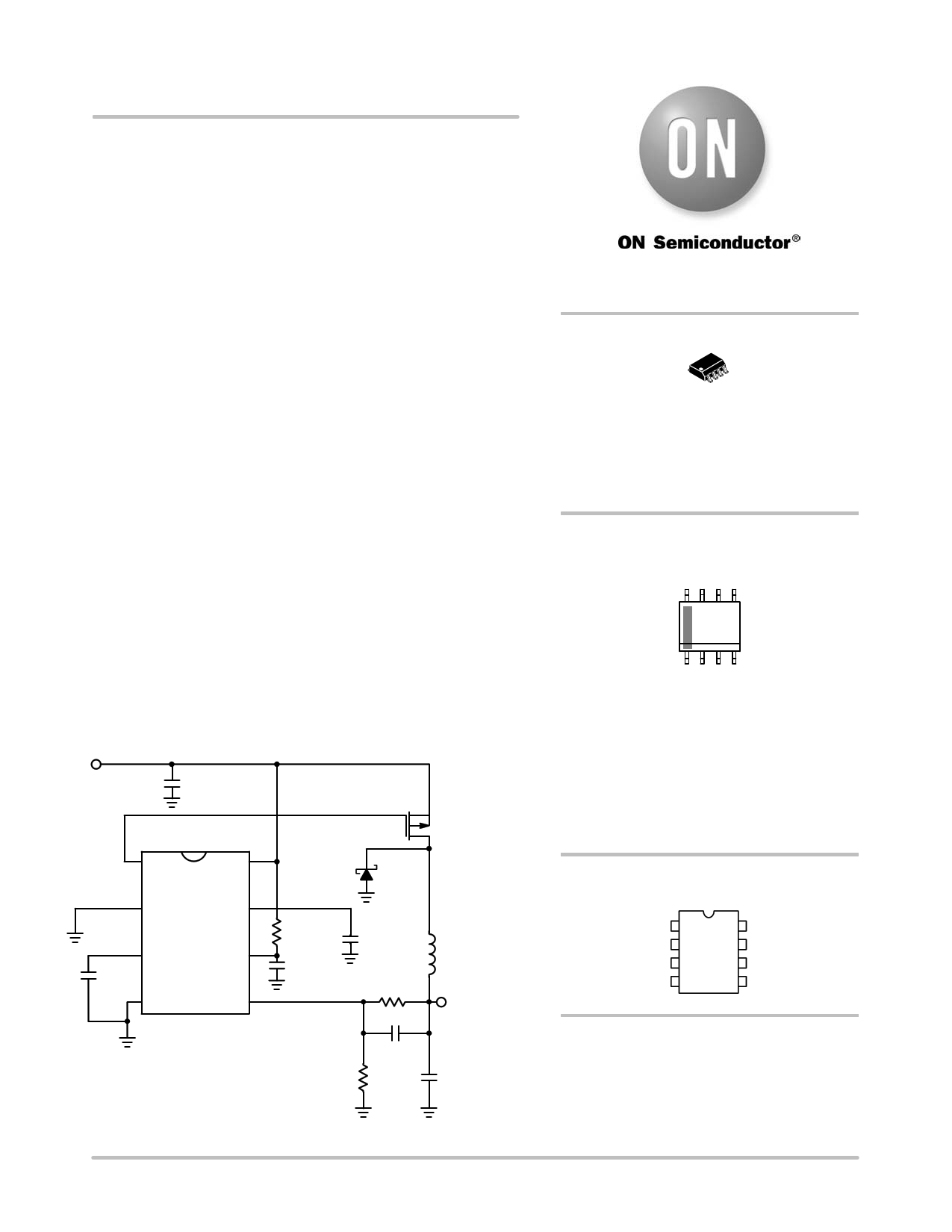
5.0 V−12 V
CIN
47 mF
VGATE
VGATE
PGND
VC
CS
COSC
COSC
470 pF
GND
VCC
VFB
MBRS360
D1
MP1
IRF7416
RVCC
100 W
CVCC
0.1 mF
CS
0.1 mF
RB
2.5 kW
RA
1.5 kW
CRR
0.1 mF
L
4.7 mH
VO
3.3 V @ 3 A
CO
100 mF × 2
Figure 1. Typical Application Diagram
© Semiconductor Components Industries, LLC, 2005
October, 2005 − Rev. 11
1
http://onsemi.com
8
1
SOIC−8
D SUFFIX
CASE 751
MARKING DIAGRAM
8
51031
ALYWx
G
1
51031 = Device Code
A = Assembly Location
L = Wafer Lot
Y = Year
W = Work Week
x = Continuation of Device Code
x = Y or G
G = Pb−Free Package
PIN CONNECTIONS
1
VGATE
PGND
COSC
GND
VC
CS
VCC
VFB
ORDERING INFORMATION
See detailed ordering and shipping information in the package
dimensions section on page 2 of this data sheet.
Publication Order Number:
CS51031/D
1 page 
CS51031
Startup
The CS51031 has an externally programmable Soft−Start
feature that allows the output voltage to come up slowly,
preventing voltage overshoot on the output.
At startup, the voltage on all pins is zero. As VCC rises, the
VC voltage along with the internal resistor RG keeps the
P−Ch FET off. As VCC and VC continue to rise, the oscillator
capacitor (COSC ) and the Soft−Start/Fault Timing capacitor
(CS) charges via internal current sources. COSC gets charged
by the current source IC and CS gets charged by the IT source
combination described by:
ǒ ǓICS + IT *
IT
55
)
IT
5
The internal Holdoff Comparator ensures that the external
P−Ch FET is off until VCS > 0.7 V, preventing the GATE
flip−flop (F2) from being set. This allows the oscillator to
reach its operating frequency before enabling the drive
output. Soft−Start is obtained by clamping the VFB
comparator’s (A6) reference input to approximately 1/2 of
the voltage at the CS pin during startup, permitting the
control loop and the output voltage to slowly increase. Once
the CS pin charges above the Holdoff Comparator trip point
of 0.7 V, the low feedback to the VFB Comparator sets the
GATE flip−flop during COSC’s charge cycle. Once the
GATE flip−flop is set, VGATE goes low and turns on the
P−Ch FET. When VCS exceeds 2.3 V, the CS charge sense
comparator (A4) sets the VFB comparator reference to
1.25 V completing the startup cycle.
Lossless Short Circuit Protection
The CS51031 has “lossless” short circuit protection since
there is no current sense resistor required. When the voltage
at the CS pin (the fault timing capacitor voltage) reaches
2.5 V during startup, the fault timing circuitry is enabled by
A2. During normal operation the CS voltage is 2.6 V. During
a short circuit or a transient condition, the output voltage
moves lower and the voltage at VFB drops. If VFB drops
below 1.15 V, the output of the fault comparator goes high
and the CS51031 goes into a fast discharge mode. The fault
timing capacitor, CS, discharges to 2.4 V. If the VFB voltage
is still below 1.15 V when the CS pin reaches 2.4 V, a valid
fault condition has been detected. The slow discharge
comparator output goes high and enables gate G5 which sets
the slow discharge flip−flop. The VGATE flip−flop resets and
the output switch is turned off. The fault timing capacitor is
slowly discharged to 1.5 V. The CS51031 then enters a
normal startup routine. If the fault is still present when the
fault timing capacitor voltage reaches 2.5 V, the fast and
slow discharge cycles repeat as shown in figure 3.
If the VFB voltage is above 1.15 V when CS reaches 2.4 V
a fault condition is not detected, normal operation resumes
and CS charges back to 2.6 V. This reduces the chance of
erroneously detecting a load transient as a fault condition.
2.6 V
VCS 2.4 V
1.5 V
0.7 V
0V
VGATE
1.25 V
1.15 V
VFB
S1
TSTART
START
S2 S1
NORMAL OPERATION
S2
S3
S3 S1
S2
S3
S3
td1 tFAULT
tRESTART td2
tFAULT
FAULT
2.5 V
0V
Figure 3. Voltage on Start Capacitor (VGS), the Gate (VGATE), and in the
Feedback Loop (VFB), During Startup, Normal and Fault Conditions
http://onsemi.com
5
5 Page | ||
| Páginas | Total 10 Páginas | |
| PDF Descargar | [ Datasheet CS51031.PDF ] | |
Hoja de datos destacado
| Número de pieza | Descripción | Fabricantes |
| CS51031 | Fast PFET Buck Controller Does Not Require Compensation | Cherry Semiconductor Corporation |
| CS51031 | Fast P-Ch FET Buck Controller | ON Semiconductor |
| CS51033 | Fast PFET Buck Controller Does Not Require Compensation | Cherry Semiconductor Corporation |
| CS51033 | Fast P-Ch FET Buck Controller | ON Semiconductor |
| Número de pieza | Descripción | Fabricantes |
| SLA6805M | High Voltage 3 phase Motor Driver IC. |
Sanken |
| SDC1742 | 12- and 14-Bit Hybrid Synchro / Resolver-to-Digital Converters. |
Analog Devices |
|
DataSheet.es es una pagina web que funciona como un repositorio de manuales o hoja de datos de muchos de los productos más populares, |
| DataSheet.es | 2020 | Privacy Policy | Contacto | Buscar |