|
|
|
PDF EM6617 Data sheet ( Hoja de datos )
| Número de pieza | EM6617 | |
| Descripción | Ultra-low power microcontroller | |
| Fabricantes | EM Microelectronic | |
| Logotipo | ||
Hay una vista previa y un enlace de descarga de EM6617 (archivo pdf) en la parte inferior de esta página. Total 65 Páginas | ||
|
No Preview Available !
EM MICROELECTRONIC - MARIN SA
EM6617
Ultra Low Power Microcontroller with ADC AND EEPROM
Features
• Low Power - 3.2 µA active mode, ADC off
- 9.0 µA active mode, ADC on
- 0.6 µA standby mode
- 0.1µA sleep mode
@ 3.0V, 32kHz, 25°C
• Voltage range logic incl. EEPROM 2.0 to 5.5 V
• System operating clock : 32 or 128KHz (metal option)
• Voltage range for the ADC is 2.6 to 5.5 V
• 2 clocks per instruction cycle
• 72 basic instructions
• ROM 3k × 16 bit
• RAM 128 × 4 bit
• E2PROM 64 × 8 bit
• Voltage Level Detector, 3 levels software
selectable :2.2, 2.5, 3.0 V
• 2 channel ADC, successive approximation method;
conversion time at 32 kHz : 305µs
• Max. 12 inputs (3 ports); port A, port B, port C
• Max. 8 outputs (2 ports); port B, port C
• Serial Write Buffer, 256 bit wide , 4 bit rates
• Oscillation supervisor and timer watchdog
• Universal 10-bit counter, PWM, event counter
• 8 internal interrupt sources (2 × timer , 2 × prescaler,
ADC, VLD, FIFO, EEPROM)
• 4 external interrupt sources (input port A )
• Frequency output; 32kHz, 2kHz, 1kHz, PWM
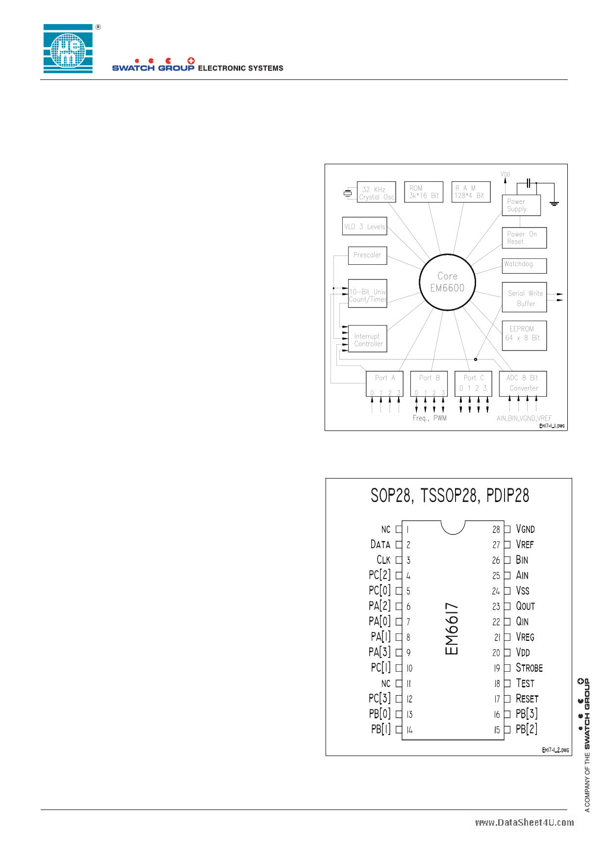
Figure 1. Architecture
Figure 2. Pin Configuration
Description
The EM6617 is an advanced single chip CMOS 4-bit
microcontroller. It contains ROM, RAM, power on reset,
watchdog timer, oscillation detection circuit, combined
timer , event counter, prescaler, E2PROM, 2 channel
ADC, serial write buffer, voltage level detector and
several clock functions. The low voltage feature and low
power consumption make it the most suitable controller
for battery, stand alone and mobile equipment. The
EM6617 is manufactured using EM Microelectronic’s
advanced low power (ALP) CMOS Process.
Typical Applications
• Sensor & detector interface
• Heat meter interface
• Security systems
• Household equipment controls
• Automotive controls
• Measurement equipment
• R/F and IR. control
• Voltage control
Copyright © 2005, EM Microelectronic-Marin SA
1
www.emmicroelectronic.com
1 page 
EM6617
2. Typical configurations
Full range ADC : Vref = VDD, Vgnd = VDD/2.
For power saving one might connect the Vgnd resistor divider chain onto a port B output. This output should be
driving VDD during the conversion and driving VSS or high impedance in the ADC off state.
Figure 3. Typical Application, Full Range
Main power
Full
range
ADC
+
-
32 KHz
Reset
Strobe
VDD Vreg VSS
Ain
Bin
≈
Port A
Port B
Port C
Vref VDD
Vgnd
Vss
VDD, or port driven
R1
>1.3V
R1
Vss
VDD
Vgnd
Vss
Limited range ADC : VDD > Vref > Vgnd, Vgnd=VDD/2.
For power saving one might connect the Vgnd and the Vref resistor divider chain onto a port B output to VSS. This
output should be driving VDD during the conversion and driving Vss or high impedance in the ADC off state.
Figure 4. Typical Application, Limited Range
Main power
+| Vref - Vgnd |
32 KHz
Reset
Strobe
VDD Vreg Vss
Ain
Bin
Port A
Vref
Port B
Port C
Vgnd
limited
range
ADC
+
-
Vdd
Vref
Vgnd
Vss
≈ -| Vref - Vgnd |
Vss or Vgnd
Vref Vdd or Port B driven
R1 >1.3V
C1
R1
Vss
other possibility: VREF = VregLogic, VGND = VregLogic/2
For power saving one might connect the Vgnd resistor divider chain from VregLogic onto a port B output. This
output should be driving VSS during the conversion and driving ‘high impedance’ in the ADC off state.
Copyright © 2005, EM Microelectronic-Marin SA
5
www.emmicroelectronic.com
5 Page 
Table 5.4.1 Watchdog Timer Register RegSysCntl2
Bit Name
Reset
R/W
3
WDReset
0
R/W
2
SleepEn
0
R/W
1
WDVal1
0
R
0
WDVal0
0
R
Table 5.4.2 Watchdog Control Register RegSysCntl3
Bit Name
Reset
R/W
3
Vref1/2Sel
0
R/W
2 --
0 R/W
1
NoOscWD
0
R/W
0
NoLogicWD
0
R/W
EM6617
Description
Reset the Watchdog
1 -> Resets the Logic Watchdog
0 -> No action
The Read value is always '0'
See Operating modes (sleep)
Watchdog timer data Ck[1] divided by 4
Watchdog timer data Ck[1] divided by 2
Description
Reference selection for the ADC
always reads 0
No oscillation supervisor
No logic watchdog
5.5 CPU State after Reset
Reset initializes the CPU as shown in Table 5.5.1 below.
Table 5.5.1 Initial CPU Value after Reset.
Name
Bits
Program counter 0
12
Program counter 1
12
Program counter 2
12
Stack pointer
2
Index register
7
Carry flag
1
Zero flag
1
Halt 1
Instruction register
16
Symbol
PC0
PC1
PC2
SP
IX
CY
Z
HALT
IR
Periphery registers 4 Reg.
Initial Value
hex 000 (as a result of Jump 0)
Undefined
Undefined
PSP[0] selected
Undefined
Undefined
Undefined
0
Jump 0
See peripheral memory map
Copyright © 2005, EM Microelectronic-Marin SA
11
www.emmicroelectronic.com
11 Page | ||
| Páginas | Total 65 Páginas | |
| PDF Descargar | [ Datasheet EM6617.PDF ] | |
Hoja de datos destacado
| Número de pieza | Descripción | Fabricantes |
| EM6617 | Ultra-low power microcontroller | EM Microelectronic |
| Número de pieza | Descripción | Fabricantes |
| SLA6805M | High Voltage 3 phase Motor Driver IC. |
Sanken |
| SDC1742 | 12- and 14-Bit Hybrid Synchro / Resolver-to-Digital Converters. |
Analog Devices |
|
DataSheet.es es una pagina web que funciona como un repositorio de manuales o hoja de datos de muchos de los productos más populares, |
| DataSheet.es | 2020 | Privacy Policy | Contacto | Buscar |