|
|
|
PDF EM6682 Data sheet ( Hoja de datos )
| Número de pieza | EM6682 | |
| Descripción | Ultra Low Power 8-pin Microcontroller | |
| Fabricantes | EM Microelectronic | |
| Logotipo | ||
Hay una vista previa y un enlace de descarga de EM6682 (archivo pdf) en la parte inferior de esta página. Total 30 Páginas | ||
|
No Preview Available !
R EM MICROELECTRONIC - MARIN SA
EM6682
Ultra Low Power 8-pin Microcontroller
Features
True Low Power:
4.0 µA active mode
3.0 µA standby mode
0.35 µA sleep mode
@ 1.5V, 32kHz, 25°C
Low Supply Voltage 0.9 V to 5.5 V
Medium voltage version: 1.4V to 5.5V
Low voltage version: 0.9V to 1.8V
No external component needed
Available in TSSOP-8/14, SO-8/14 packages and die
4-bit ADC or 12 levels Supply Voltage Level
Detector (SVLD)
Max 4 (5*) outputs with 2 high drive outputs of 10mA
Max. 5 (6*) inputs
Sleep Counter Reset (automatic wake-up from sleep
mode (EM patent))
Mask ROM 1536 × 16 bits
RAM 80 × 4 bits
Internal RC oscillator 32 kHz – 800 kHz
2 clocks per instruction cycle
72 basic instructions
External CPU clock source possible
Watchdog timer (2 sec)
Power-On-Reset with Power-Check on Start-Up
3 wire serial port , 8 bit, master and slave mode
Universal 10-bit counter, PWM, event counter
Prescaler down to 1 Hz (freq. = 32 kHz)
Frequency output 1Hz, 2048 Hz, Fosc, PWM
6 internal interrupt sources ( 2×10-bit counter, 2×
prescaler, SVLD, Serial Interface)
2 external interrupt sources (port A)
Description
The EM6682 is an ultra-low voltage, low power
microcontroller coming in a package as small as 8-pin
TSSOP and working up to 0.4 MIPS. It comes with an
integrated 4-bit ADC and 2 high drive outputs of 10mA and
it requires no external component. It has a sleep counter
reset allowing automatic wake-up from sleep mode. It is
designed for use in battery-operated and field-powered
applications requiring an extended lifetime. A high
integration level make it an ideal choice for cost sensitive
applications.
The EM6682 contains the equivalent of 3kB mask ROM
and a RC oscillator with frequencies between 32 and
800kHz selectable by metal option or register. It also has
a power-on reset, watchdog timer, 10 bit up/down
counter, PWM and several clock functions.
Tools include windows-based simulator and emulator.
The EM6682 simulator is usable for most of the
EM6682 functions.
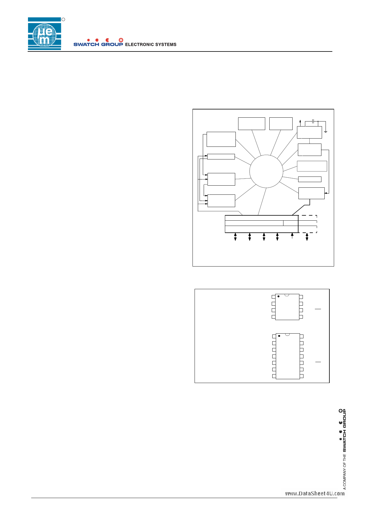
Figure 1. Architecture
Stable
RC oscillator
32 - 800kHz
ROM
1536 x 16Bit
RAM
80 x 4Bit
Prescaler
10-Bit Univ
Count/Timer
Core
EM6600
Interrupt
Controller
VDD
VDD
Power Supply
Voltage reg.
Power on
Reset
Sleep Counter
Reset
Watchdog
4-bit ADC
SVLD check
Port A
Serial Interface
PA0 PA1 PA2
Reset
PA3 PA4 *PA5
PA1 & PA2: high-drive outputs (10mA)
* PA5 available only in 14-pin package and in die
Figure 2. Pin Configuration
TSSOP-8, SO-8
PA0 1
8 VDD
PA1 2 EM6682 7 VREG
PA2 3
6 PA4 (reset)
PA3 4
5 VSS
TSSOP-14, SO-14
NC 1
14 NC
PA0 2
13 VDD
PA1 3
12 VREG
PA2 4 EM6682 11 PA5
PA3 5
10 PA4 (reset)
NC 6
9 VSS
NC 7
8 NC
Typical Applications
Household appliances
Safety and security devices
Automotive controls
Sensor interfaces
Watchdog
Intelligent ADC
Driver (LED, triac)
Copyright © 2006, EM Microelectronic-Marin SA
1
www.emmicroelectronic.com
1 page 
R
EM6682
2. Operating modes
The EM6682 can operate in three different modes of which 2 are low-power dissipation modes (Stand-By and Sleep). The
modes and transitions between them are shown in Figure 5.
1.) Active mode
2.) Stand-By mode
3.) Sleep mode
Figure 5. EM6682 operating mode transitions
START-UP
RC oscilator
running
8 oscillator
periods
RESET
reset synchronizer
and
Power-Check
Power-On-Reset & Power Check Level
resetPortA
WDreset
PORwPC
PORwPC
PORwPC
POWER-ON
POR static level
Power-Check Active
PORwPC
Reset-pad
WDreset
8 CPU clock
periods
ACTIVE
or running
mode
HALT instruction
interrupt/event
STAND-BY
or HALT
mode
Clocks active
SleepResCnt
WakeUp on
Change
SLEEP
Everything stopped
Registers and
RAM keep their value
Sleep bit set
It is possible to initiate Power-Check at every reset by metal option. In this case, in order to change from reset
state to active state, the supply voltage must be higher than the active Power-Check selection level. This
selection level corresponds to the SVLD level 5 (default) after power-up or to the SVLD level selection active at
the end of the reset state.
2.1 ACTIVE Mode
The active mode is the actual CPU running mode. Instructions are read from the internal ROM and executed by
the CPU. Leaving the active mode: via the halt instruction to go into standby mode, writing the SLEEP bit to go
into Sleep mode or detecting the reset to go into reset mode.
2.2 STANDBY (Halt) Mode
Executing a HALT instruction puts the EM6682 into standby mode. The voltage regulator, oscillator, watchdog
timer, interrupts, timers and counters are operating. However, the CPU stops since the clock related to
instruction execution stops. Registers, RAM and I/O pins retain their states prior to STANDBY mode. STANDBY
is cancelled by a RESET or an Interrupt request if enabled.
2.3 SLEEP Mode
Writing to the Sleep bit in the RegSysCntl1 register puts the EM6682 in sleep mode. The oscillator stops and
most functions of the EM6682 are inactive. To be able to write to the Sleep bit, the SleepEn bit in RegSysCntl2
must first be set to "1". In SLEEP mode only the voltage regulator is active to maintain the RAM data integrity, all
other functions are in reset state. SLEEP mode may be cancelled by Wake/Up on change, external reset or by
Sleep Reset Counter if any of them is enabled.
Waking up from sleep mode may takes some time to guarantee stable oscillation. Coming back from sleep mode
puts the EM6682 in reset state and as such reinitializes all registers to their reset value. Waking up from sleep
mode clears the Sleep flag but not the SleepEn bit. Inspecting the SleepEn allows to determine if the EM6682
was powered up (SleepEn = "0") or woken from sleep mode (SleepEn = "1").
Copyright © 2005, EM Microelectronic-Marin SA
5
www.emmicroelectronic.com
5 Page 
R
EM6682
5. Oscillator and Prescaler
5.1 RC Oscillator or external Clock
EM6682 can use the internal RC oscillator or external clock source for its operation.
The built-in RC oscillator without external components generates the system operating clock for the CPU and peripheral
blocks. The RC oscillator is supplied by the regulated voltage in medium voltage version.
The RC oscillator can generate 2 basic frequencies selectable by metal option or by registers 512kHz or 800kHz selected by
RegMFP1[3].
In the output of the RC oscillator, a selectable divider allows generating 512kHz, 256kHz, 128kHz, 64kHz or 32kHz. If the
basic frequency is 800kHz the divider can generate 800kHz, 400kHz, 200kHz, 100kHz or 50kHz. The division factor is given
by the register RegMFP1[2:0] (see table 5.2.1). These frequencies can be used for the CPU clock (if the external clock is not
selected). Another divider generates automatically SysClk as close as possible to 32kHz or 50kHz depending on the basic
frequency selected. This clock is used by the 15 stages prescaler that generated clock for the peripherals.
For a full software compatibility with the EM6680 and EM6681, the division factor of the RC clock can be fix by metal option. It
means that it is not necessary to set the RC frequency by software. To get a good frequency stability over the supply in
low voltage it is possible, by metal option, to select a 128kHz (or 200kHz) RC oscillator. In this case the division
factor is fixed to 1 meaning that the CPU runs at 128kHz (or 200kHz) and SysClk at 32kHz (or 50kHz). It is not
permitted to use the EM6682 at LV over 128kHz.
Please note that Vddmin must be higher when working with higher frequencies – see figure 30.
After POR the circuit always starts with the internal RC oscillator, but it can be switched to the external clock by setting the
ExtCPUclkON bit in the register RegPresc. The external clock is input at PA[1] and must be in range from min. 10Khz to
max. 1MHz. With this external frequency input all timing for peripherals change and the special 4 stage freq. divider must be
adapted to best suit the applied external frequency to keep 32/50kHz System clock as close as possible. The system clock
must be less than 64kHz. The external clock source must be a square wave with full amplitude from Vss to Vdd. See Table
5.2.2 for advised special divisions depending on the external clock frequency.
Switching from internal RC oscillator to External clock or back from External clock to RC oscillator is made without generating
a glitch on the internal clock. Once the circuit is running on the external Clock one can disable the RC oscillator by setting the
RCoscOff bit in RegSCntl2 to ‘1’.
In sleep mode the oscillator is stopped. It can be stopped also by setting the RCoscOff bit. This bit can be set only if
ExtClkOn was set before, indicating that the CPUck was switched from the internal RC oscillator to the external clock which
MUST be present. If the External Clock stops without going into Sleep mode first the EM6682 can block and only POR can
reset it.
Figure 8 below shows the connection of the RC oscillator and external clock and generation of CPUclk and System clock =
SysClk which is divided by the special 4 stage Freq. Divider if needed as described in 5.2 and prescaler described in 5.3.
97H
Figure 8. Clock source for CPU or system peripherals
RegOscTrim1
[3:0]
OscTrim[7:0]
RC SYSTEM
RC oscilator
512kHz – 800kHz
Frequency
divider
RegOscTrim1
[3:0]
Metal option
or register
selector
RegMFP1
[3]
RegMFP1
[2:0]
Metal option
or register
selector
MUX
PA[1]
External clock
10kHz – 1MHz
ExtCPUclkON
MUX
Automatic clock selection
SysClk = 32kHz or 50kHz
Frequency
divider
MUX
PAout[2]
foutSel[1:0]
MUX
MUX
Sout
PAout[2]
Ck[14] ResSys
MUX
CPUclk
PA[5]
PA[2]
Peripherals
SysClk
PRESCALER
LOW 15 stages divider
Copyright © 2005, EM Microelectronic-Marin SA
11
www.emmicroelectronic.com
11 Page | ||
| Páginas | Total 30 Páginas | |
| PDF Descargar | [ Datasheet EM6682.PDF ] | |
Hoja de datos destacado
| Número de pieza | Descripción | Fabricantes |
| EM6680 | Ultra Low Power 8-pin Microcontroller | EM Microelectronic |
| EM6682 | Ultra Low Power 8-pin Microcontroller | EM Microelectronic |
| Número de pieza | Descripción | Fabricantes |
| SLA6805M | High Voltage 3 phase Motor Driver IC. |
Sanken |
| SDC1742 | 12- and 14-Bit Hybrid Synchro / Resolver-to-Digital Converters. |
Analog Devices |
|
DataSheet.es es una pagina web que funciona como un repositorio de manuales o hoja de datos de muchos de los productos más populares, |
| DataSheet.es | 2020 | Privacy Policy | Contacto | Buscar |