|
|
|
PDF CS5364 Data sheet ( Hoja de datos )
| Número de pieza | CS5364 | |
| Descripción | 4-Channel A/D Converter | |
| Fabricantes | Cirrus Logic | |
| Logotipo | ||
Hay una vista previa y un enlace de descarga de CS5364 (archivo pdf) en la parte inferior de esta página. Total 30 Páginas | ||
|
No Preview Available !
CS5364
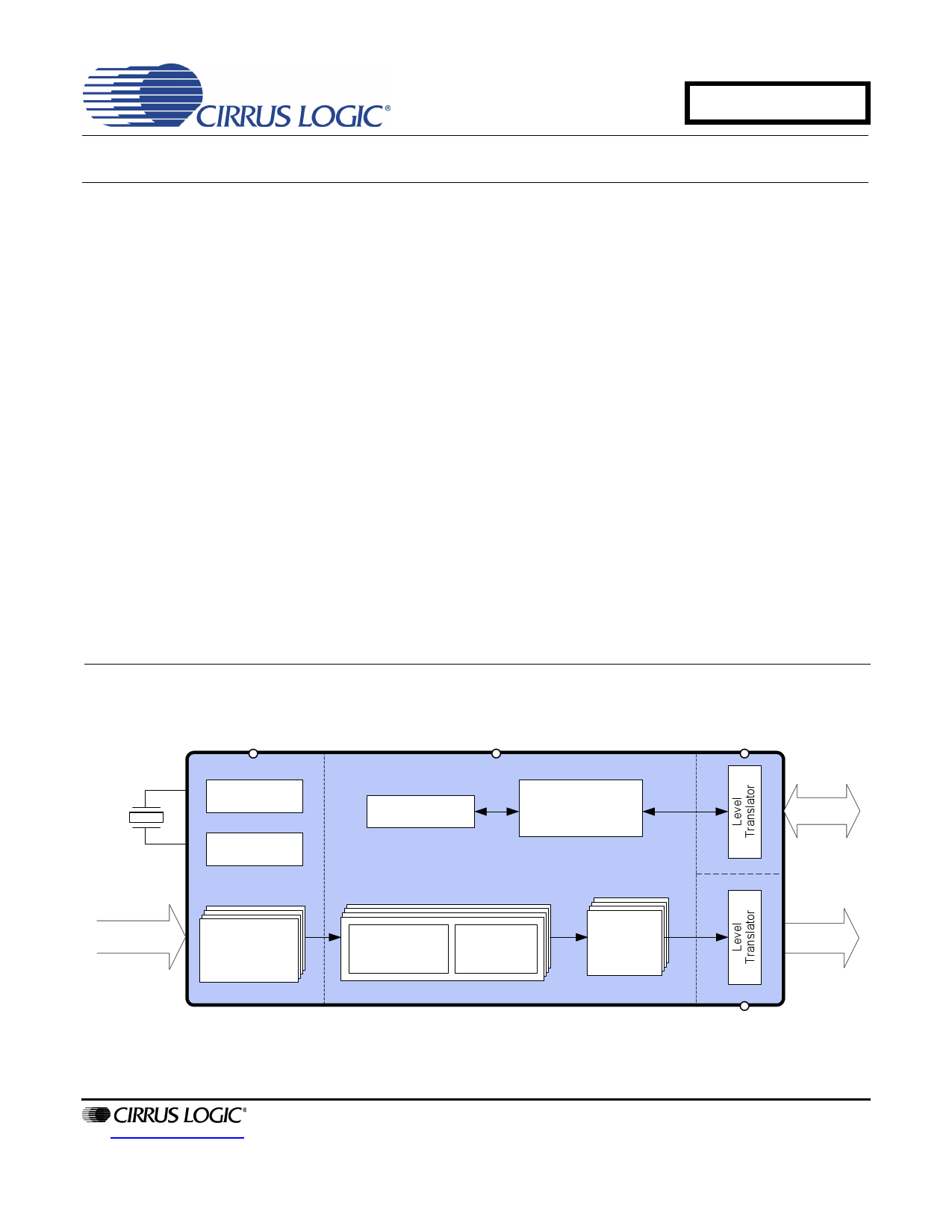
114 dB, 192 kHz, 4-Channel A/D Converter
Features
Advanced Multi-bit Delta-Sigma Architecture
24-Bit Conversion
114 dB Dynamic Range
-105 dB THD+N
Supports Audio Sample Rates up to 216 kHz
Selectable Audio Interface Formats
– Left-Justified, I²S, TDM
– 4-Channel TDM Interface Formats
Low Latency Digital Filter
Less than 365 mW Power Consumption
On-Chip Oscillator Driver
Operation as System Clock Master or Slave
Auto-Detect Speed in Slave Mode
Differential Analog Architecture
Separate 1.8 V to 5 V Logic Supplies for
Control and Serial Ports
High-Pass Filter for DC Offset Calibration
Overflow Detection
Footprint Compatible with the 8-Channel
CS5368
Additional Control Port Features
Supports I²C or SPI™ Control Interface per
specifications on page 17 and page 18
Individual Channel HPF Disable
Overflow Detection for Individual Channels
Mute Control for Individual Channels
Independent Power-Down Control per Channel
Pair
VA
5V
Voltage
Reference
Internal
Oscillator
4 Differential
Analog Inputs
Multi-bit
ADC
http://www.cirrus.com
VD
3.3 - 5V
Configuration
Registers
Control Interface
I2C, SPI
or Pins
VLC
1.8 - 5V
Device
Control
Decimation
Filter
High Pass
Filter
Serial
Audio Out
PCM or
TDM
Copyright Cirrus Logic, Inc. 2014
(All Rights Reserved)
Digital
Audio
VLS
1.8 - 5V
JUL '14
DS625F5
1 page 
CS5364
LIST OF TABLES
Table 1. Power Supply Pin Definitions ...................................................................................................... 19
Table 2. DIF1 and DIF0 Pin Settings ........................................................................................................ 23
Table 3. M1 and M0 Settings .................................................................................................................... 23
Table 4. Frequencies for 48 kHz Sample Rate using LJ/I²S ..................................................................... 25
Table 5. Frequencies for 96 kHz Sample Rate using LJ/I²S ..................................................................... 25
Table 6. Frequencies for 192 kHz Sample Rate using LJ/I²S ................................................................... 25
Table 7. Frequencies for 48 kHz Sample Rate using TDM ....................................................................... 25
Table 8. Frequencies for 48 kHz Sample Rate using TDM ....................................................................... 25
Table 9. Frequencies for 96 kHz Sample Rate using TDM ....................................................................... 26
Table 10. Frequencies for 96 kHz Sample Rate using TDM ..................................................................... 26
Table 11. Frequencies for 192 kHz Sample Rate using TDM ................................................................... 26
Table 12. Frequencies for 192 kHz Sample Rate using TDM ................................................................... 26
DS625F5
5
5 Page 
CS5364
DC POWER
MCLK = 12.288 MHz; Master Mode. GND = 0 V.
Parameter
Symbol Min Typ Max Unit
Power Supply Current
(Normal Operation)
Power Supply Current
(Power-Down) (Note 1)
Power Consumption
(Normal Operation)
(Power-Down) (Note 1)
VA = 5 V
VX = 5 V
VD = 5 V
VD = 3.3 V
VLS, VLC = 5 V
VLS, VLC = 3.3 V
VA = 5 V
VLS, VLC,VD = 5 V
All Supplies = 5 V
VA = 5 V, VD = VLS = VLC = 3.3 V
IA
IX
ID
ID
IL
IL
IA
ID
-
-
-
-
-
-
-
-
-
-
-
-
-
-
51 56 mA
4 8 mA
44 48 mA
25 28 mA
3 4 mA
1 2 mA
50 - A
500 - A
mW
510 580 mW
360 419 mW
2.75 - mW
1. Power-Down is defined as RST = LOW with all clocks and data lines held static at a valid logic level.
LOGIC LEVELS
Parameter
Symbol Min Typ Max Units
High-Level Input Voltage
Low-Level Input Voltage
High-Level Output Voltage at 100 A load
Low-Level Output Voltage at -100 A load
SDA Low-Level Output Voltage at -2 mA load
%VLS/VLC
%VLS/VLC
%VLS/VLC
%VLS/VLC
%VLC
VIH
VIL
VOH
VOL
VOL
70
-
85
-
-
- -%
- 30 %
- -%
- 15 %
-
TBD
%
OVFL Current Sink
-4 mA
Input Leakage Current
logic pins only
Iin
-10
-
10 A
PSRR, VQ AND FILT+ CHARACTERISTICS
MCLK = 12.288 MHz; Master Mode. Valid with the recommended capacitor values on FILT+ and VQ as shown in
the “Typical Connection Diagram”.
Parameter
Power Supply Rejection Ratio at (1 kHz)
VQ Nominal Voltage
Output Impedance
Maximum allowable DC current source/sink
Filt+ Nominal Voltage
Output Impedance
Maximum allowable DC current source/sink
Symbol
PSRR
Min
-
-
-
Typ
65
VA/2
25
10
VA
4.4
10
Max
-
-
-
Unit
dB
V
k
A
V
k
A
DS625F5
11
11 Page | ||
| Páginas | Total 30 Páginas | |
| PDF Descargar | [ Datasheet CS5364.PDF ] | |
Hoja de datos destacado
| Número de pieza | Descripción | Fabricantes |
| CS5360 | 24-Bit Stereo A/D Converter for Digital Audio | Cirrus Logic |
| CS5360 | (CS5334 - CS5360) Evaluation Board | Cirrus Logic |
| CS5360-BS | 24-Bit Stereo A/D Converter for Digital Audio | Cirrus Logic |
| CS5360-KS | 24-Bit Stereo A/D Converter for Digital Audio | Cirrus Logic |
| Número de pieza | Descripción | Fabricantes |
| SLA6805M | High Voltage 3 phase Motor Driver IC. |
Sanken |
| SDC1742 | 12- and 14-Bit Hybrid Synchro / Resolver-to-Digital Converters. |
Analog Devices |
|
DataSheet.es es una pagina web que funciona como un repositorio de manuales o hoja de datos de muchos de los productos más populares, |
| DataSheet.es | 2020 | Privacy Policy | Contacto | Buscar |