|
|
|
PDF 5962-0721302QXC Data sheet ( Hoja de datos )
| Número de pieza | 5962-0721302QXC | |
| Descripción | 500MHz Rail-to-Rail Amplifiers | |
| Fabricantes | Intersil Corporation | |
| Logotipo | ||
Hay una vista previa y un enlace de descarga de 5962-0721302QXC (archivo pdf) en la parte inferior de esta página. Total 5 Páginas | ||
|
No Preview Available !
www.DataSheet4U.com
®
5962-0721301QXC, 5962-0721302QXC,
5962-0721303QYC
Data Sheet
October 17, 2007
FN6478.1
500MHz Rail-to-Rail Amplifiers
The 5962-0721301QXC, 5962-0721302QXC and
5962-0721303QYC are fully DSCC SMD compliant parts and
the SMD data sheets are available on the DSCC website
(http://www.dscc.dla.mil/ programs/specfind/default.asp). The
5962-0721301QXC is electrically equivalent to the EL8202,
the 5962-0721302QXC is electrically equivalent to the
EL8203, and the 5962-0721303QYC is electrically equivalent
to the EL8403. Reference equivalent “EL” data sheet for
additional information. These parts are dual and quad rail-to-
rail amplifiers with a -3dB bandwidth of 500MHz and slew rate
of 600V/µs.
Running off a low supply current of 13.5mA per channel, the
5962-0721301QXC, 5962-0721302QXC, and 5962-
0721303QYC also feature inputs that go to 0.15V below the
VS- rail. The 5962-0721301QXC and 5962-0721302QXC
are dual channel amplifiers. The 5962-0721303QYC is a
quad channel amplifier.
The 5962-0721301QXC includes a fast-acting
disable/power-down circuit with a 25ns disable and a 200ns
enable, the 5962-0721301QXC is ideal for multiplexing
applications.
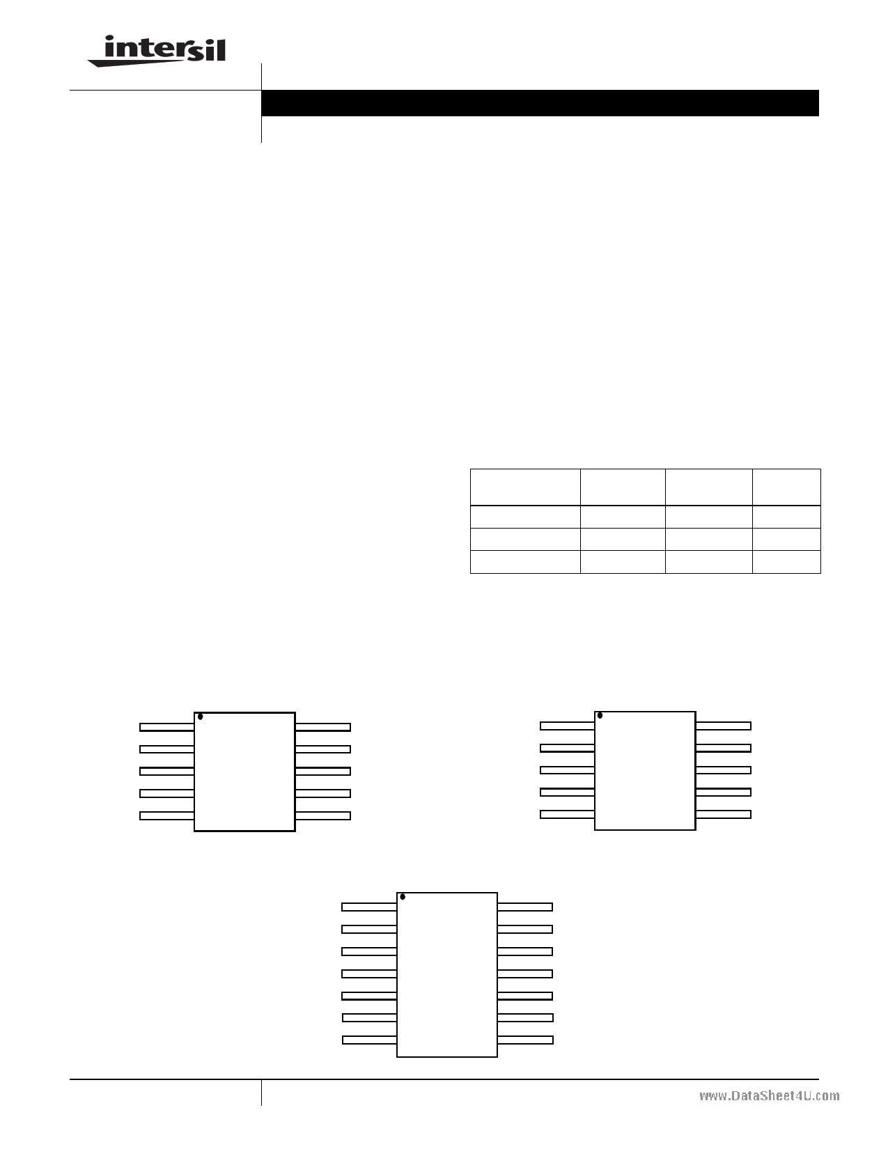
Pinouts
5962-0721301QXC
(10 LD FLATPACK)
TOP VIEW
1 INA+
INA- 10
2
CEA
OUTA 9
3 VS-
4 CEB
VS+ 8
OUTB 7
5
INB+
INB- 6
Features
• 500MHz -3dB bandwidth
• 600V/µs slew rate
• Supplies from 3V to 5.5V
• Rail-to-rail output
• Input to 0.15V below VS-
• Fast 25ns disable (5962-0721301QXC only)
Applications
• Video amplifiers
• Portable/hand-held products
• Communications devices
Ordering Information
PART
NUMBER
PART
MARKING
PACKAGE
PKG.
DWG. #
5962-0721301QXC 07213 01QXC 10 Ld Flat Pack K10.A
5962-0721302QXC 07213 02QXC 10 Ld Flat Pack K10.A
5962-0721303QYC 07213 03QYC 14 Ld Flat Pack K14.A
NOTE: These Intersil Pb-free Hermetic packaged products employ
100% Au plate - e4 termination finish, which is RoHS compliant and
compatible with both SnPb and Pb-free soldering operations.
5962-0721302QXC
(10 LD FLATPACK)
TOP VIEW
1 INA+
INA- 10
2 NC
OUTA 9
3 VS-
VS+ 8
4 NC
OUTB 7
5
INB
INB- 6
5962-0721303QYC
(14 LD FLATPACK)
TOP VIEW
1 OUTA
OUTD 14
2 INA-
IND- 13
3 INA+
IND+ 12
4 VS+
VS- 11
5
INB
6 INB
7
OUTB
INC+ 10
INC- 9
8
OUTC
1 CAUTION: These devices are sensitive to electrostatic discharge; follow proper IC Handling Procedures.
1-888-INTERSIL or 1-888-468-3774 | Intersil (and design) is a registered trademark of Intersil Americas Inc.
Copyright © Intersil Americas Inc. 2007. All Rights Reserved.
All other trademarks mentioned are the property of their respective owners.
1 page 
www.DataSheet4U.com 5962-0721301QXC, 5962-0721302QXC, 5962-0721303QYC
14 ld FLATPACK Package Outline Drawing
e
-A-
PIN NO. 1
ID AREA
A
A
-B- D
S1
b
E1
0.004 M H A - B S D S
0.036 M H A - B S D S
Q
A
-C-
SEATING AND
BASE PLANE
E
L E2
E3 E3
c1 LEAD FINISH
-D-
L
C
-H-
BASE
METAL
(c)
b1
NOTES:
MM
(b)
SECTION A-A
1. Index area: A notch or a pin one identification mark shall be locat-
ed adjacent to pin one and shall be located within the shaded
area shown. The manufacturer’s identification shall not be used
as a pin one identification mark. Alternately, a tab (dimension k)
may be used to identify pin one.
2. If a pin one identification mark is used in addition to a tab, the lim-
its of dimension k do not apply.
3. This dimension allows for off-center lid, meniscus, and glass
overrun.
4. Dimensions b1 and c1 apply to lead base metal only. Dimension
M applies to lead plating and finish thickness. The maximum lim-
its of lead dimensions b and c or M shall be measured at the cen-
troid of the finished lead surfaces, when solder dip or tin plate
lead finish is applied.
5. N is the maximum number of terminal positions.
6. Measure dimension S1 at all four corners.
7. For bottom-brazed lead packages, no organic or polymeric mate-
rials shall be molded to the bottom of the package to cover the
leads.
8. Dimension Q shall be measured at the point of exit (beyond the
meniscus) of the lead from the body. Dimension Q minimum
shall be reduced by 0.0015 inch (0.038mm) maximum when sol-
der dip lead finish is applied.
9. Dimensioning and tolerancing per ANSI Y14.5M - 1982.
10. Controlling dimension: INCH.
K14.A MIL-STD-1835 CDFP3-F14 (F-2A, CONFIGURATION B)
14 LEAD CERAMIC METAL SEAL FLATPACK PACKAGE
INCHES
MILLIMETERS
SYMBOL MIN MAX MIN MAX NOTES
A
0.045
0.115
1.14
2.92
-
b
0.015
0.022
0.38
0.56
-
b1
0.015
0.019
0.38
0.48
-
c
0.004
0.009
0.10
0.23
-
c1
0.004
0.006
0.10
0.15
-
D
-
0.390
-
9.91
3
E
0.235
0.260
5.97
6.60
-
E1
-
0.290
-
7.11
3
E2 0.125 - 3.18
-
-
E3 0.030 - 0.76
-
7
e 0.050 BSC
1.27 BSC
-
k
0.008
0.015
0.20
0.38
2
L
0.270
0.370
6.86
9.40
-
Q
0.026
0.045
0.66
1.14
8
S1 0.005 - 0.13
-
6
M
-
0.0015
-
0.04
-
N 14
14 -
Rev. 0 5/18/94
5 FN6478.1
October 17, 2007
5 Page | ||
| Páginas | Total 5 Páginas | |
| PDF Descargar | [ Datasheet 5962-0721302QXC.PDF ] | |
Hoja de datos destacado
| Número de pieza | Descripción | Fabricantes |
| 5962-0721302QXC | 500MHz Rail-to-Rail Amplifiers | Intersil Corporation |
| Número de pieza | Descripción | Fabricantes |
| SLA6805M | High Voltage 3 phase Motor Driver IC. |
Sanken |
| SDC1742 | 12- and 14-Bit Hybrid Synchro / Resolver-to-Digital Converters. |
Analog Devices |
|
DataSheet.es es una pagina web que funciona como un repositorio de manuales o hoja de datos de muchos de los productos más populares, |
| DataSheet.es | 2020 | Privacy Policy | Contacto | Buscar |