|
|
|
PDF AN1516 Data sheet ( Hoja de datos )
| Número de pieza | AN1516 | |
| Descripción | Liquid Level Control Using a Pressure Sensor | |
| Fabricantes | Motorola Semiconductors | |
| Logotipo | ||
Hay una vista previa y un enlace de descarga de AN1516 (archivo pdf) en la parte inferior de esta página. Total 8 Páginas | ||
|
No Preview Available !
MOTOROLA
Freescale Semiconductor, Inc.
SEMICONDUCTOR APPLICATION NOTE
Order this document
by AN1516/D
Liquid Level Control Using a
Motorola Pressure Sensor
AN1516
Prepared by: JC Hamelain
Toulouse Pressure Sensor Laboratory
Semiconductor Products Sector, Toulouse, France
www.DataSheet4U.com
INTRODUCTION
Motorola Discrete Products provides a complete solution
for designing a low cost system for direct and accurate liquid
level control using an ac powered pump or solenoid valve.
This circuit approach which exclusively uses Motorola
semiconductor parts, incorporates a piezoresistive pressure
sensor with on–chip temperature compensation and a new
solid–state relay with an integrated power triac, to drive
directly the liquid level control equipment from the domestic
110/220 V 50/60 Hz ac main power line.
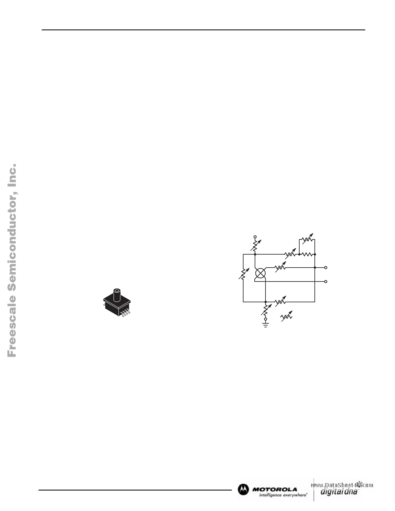
PRESSURE SENSOR DESCRIPTION
The MPXM2000 Series pressure sensor integrates
on–chip, laser–trimmed resistors for offset calibration and
temperature compensation. The pressure sensitive element
is a patented, single piezoresistive implant which replaces the
four resistor Wheatstone bridge traditionally used by most
pressure sensor manufacturers.
MPAK AXIAL PORT
CASE 1320A
Depending on the application and pressure range, the sensor
may be chosen from the following portfolio. For this application
the MPXM2010GS was selected.
Device Pressure Range Application Sensitivity*
MPXM2010GS 0 to 10 kPa
MPXM2053GS 0 to 50 kPa
MPXM2102GS 0 to 100 kPa
MPXM2202GS 0 to 200 kPa
* after proper gain adjustment
± 0.01 kPa (1 mm H2O)
± 0.05 kPa (5 mm H2O)
± 0.1 kPa (10 mm H2O)
± 0.2 kPa (20 mm H2O)
Pin 3 + VS
RS1
R1
Roff1
R2
Rp X–ducer
Roff2
Pin 2
+ Vout
Pin 4
– Vout
RS2
Pin 1 Laser Trimmed On–Chip
Figure 1. Pressure Sensor MPXM2000 Series
POWER OPTO is a trademark of Motorola Inc.
REV 2
Motorola Sensor Device Data For More Information On This Product,
© Motorola, Inc. 2002
Go to: www.freescale.com
1
1 page 
Freescale Semiconductor, Inc.
AN1516
LEVEL CONTROL MODES
This application describes two ways to keep the liquid level
constant in the tank; first, by pumping the water out if the liquid
level rises above the reference, or second, by pumping the
water in if the liquid level drops below the reference.
If pumping water out, the pump must be OFF when the liquid
level is below the reference level. To turn the pump ON, the
sensor signal must be decreased to drop the input to the
Schmitt trigger below the reference voltage. To do this, the
sensing pipe must be connected to the NEGATIVE pressure
port (back or vacuum side) of the sensor. In the condition when
the pressure increases (liquid level rises), the sensor voltage
will decrease and the pump will turn ON when the sensor
output crosses the referenced level. As pumping continues,
the level in the tank decreases (thus the pressure on the
sensor decreases) and the sensor signal increases back up
www.DataSheet4Uto.cothme trigger point where the pump was turned OFF.
In the case of pumping water into the tank, the pump must
be OFF when the liquid level is above the reference level. To
turn ON the pump, the sensor signal must be decreased to
drive the input Schmitt trigger below the reference voltage. To
do this, the sensing pipe must be connected to the POSITIVE
pressure port (top side) of the sensor. In this configuration
when the pressure on the sensor decreases, (liquid level
drops) the sensor voltage also decreases and the pump is
turned ON when the signal exceeds the reference. As
pumping continues, the water level increases and when the
maximum level is reached, the Schmitt trigger turns the pump
OFF.
ADJUSTMENTS
The sensing tube is placed into the water at a distance
below the minimum limit level anywhere in the tank. The other
end of the tube is opened to atmosphere. When the tank is
filled to the desired maximum (or minimum) level, the pressure
sensor is connected to the tube with the desired port
configuration for the application. Then the water level in the
tank is the reference.
After connecting the tube to the pressure sensor, the
module must be adjusted to control the water level. The output
voltage at TP1 is preadjusted to about 4 V (half of the supply
voltage). When the sensor is connected to the tube, the
module output is ON (lighted) or OFF. By adjusting the offset
adjust potentiometer the output is just turned into the other
state: OFF, if it was ON or the reverse, ON, if it was OFF, (the
change in the tank level may be simulated by moving the
sensing tube up or down).
The reference point TP2 shows the ON/OFF reference
voltage, and the switching point of the module is reached
when the voltage at TP1 just crosses the value of the TP2
voltage. The module is designed for about 10 mm of difference
level between ON and OFF (hysteresis).
CONCLUSION
This circuit design concept may be used to evaluate
Motorola pressure sensors used as a liquid level switch. This
basic circuit may be easily modified to provide an analog
signal of the level within the controlled range. It may also be
easily modified to provide tighter level control (± 2 mm H2O) by
increasing the gain of the first amplifier stage (decreasing RG
resistor).
The circuit is also a useful tool to evaluate the performance
of the power optocoupler MOC2A60 when driving ac loads
directly.
Motorola Sensor Device Data For More Information On This Product,
Go to: www.freescale.com
5
5 Page | ||
| Páginas | Total 8 Páginas | |
| PDF Descargar | [ Datasheet AN1516.PDF ] | |
Hoja de datos destacado
| Número de pieza | Descripción | Fabricantes |
| AN1511 | Low Voltage Gated Function Generator | Philips |
| AN1512 | All in one NE5230 | Philips |
| AN1513 | NE5205 A Cascadable Amplifier | Philips |
| AN1515 | Digital Output Angular Accelerometer | STMicroelectronics |
| Número de pieza | Descripción | Fabricantes |
| SLA6805M | High Voltage 3 phase Motor Driver IC. |
Sanken |
| SDC1742 | 12- and 14-Bit Hybrid Synchro / Resolver-to-Digital Converters. |
Analog Devices |
|
DataSheet.es es una pagina web que funciona como un repositorio de manuales o hoja de datos de muchos de los productos más populares, |
| DataSheet.es | 2020 | Privacy Policy | Contacto | Buscar |