|
|
|
PDF STP16DPPS05 Data sheet ( Hoja de datos )
| Número de pieza | STP16DPPS05 | |
| Descripción | LED Drivers | |
| Fabricantes | ST Microelectronics | |
| Logotipo | ||
Hay una vista previa y un enlace de descarga de STP16DPPS05 (archivo pdf) en la parte inferior de esta página. Total 30 Páginas | ||
|
No Preview Available !
www.DataSheet4U.com
STP16DPPS05
Low voltage 16-bit constant current
LED sink driver with output error detection and auto power-saving
Preliminary data
Features
■ Low voltage power supply down to 3 V
■ 16 constant current output channels
■ Adjustable output current through external
resistor
■ Short and open output error detection
■ Serial data IN/parallel data OUT
■ Auto power-saving
■ 3.3 V MCU-driving capability
■ Output current: 3 to 40 mA
■ 30 MHz clock frequency
■ Available in high thermal efficiency TSSOP
exposed pad
■ ESD protection: 2 kV HBM, 200 V MM
Description
The STP16DPPS05 is a monolithic, low voltage,
low current power 16-bit shift register designed for
LED panel displays. The device features a 16-bit
serial-in, parallel-out shift register that feeds a
16-bit D-type storage register. In the output stage,
sixteen regulated current sources are designed to
provide 3 to 40 mA of constant current to drive the
LEDs. The STP16DPPS05 features open and
short LED detection on the outputs. The detection
circuit checks for 3 different conditions that can
occur on the output line: short to GND, short to VO
or open line.
The data detection results are loaded in the shift
registers and shifted out via the serial line output.
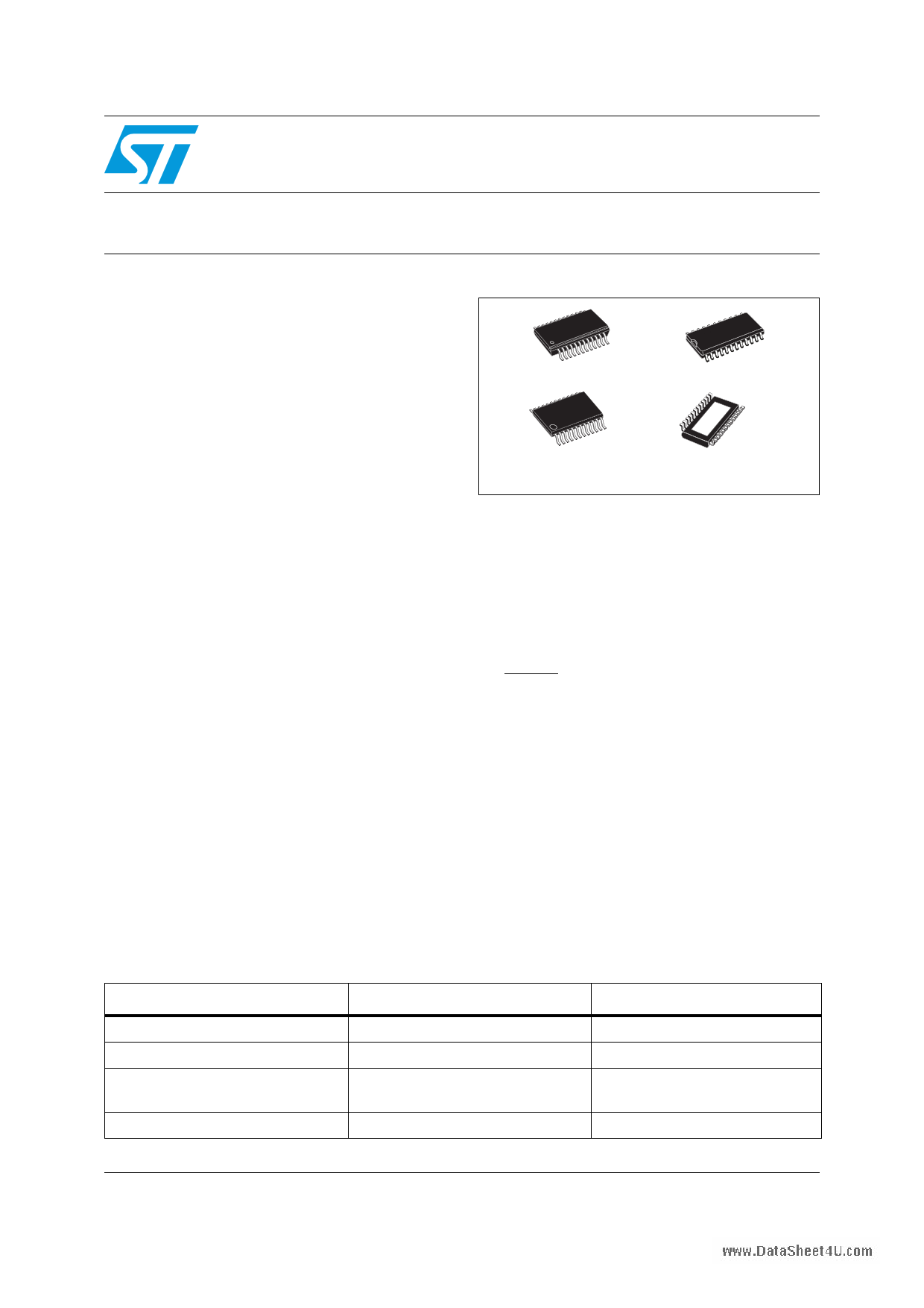
Table 1. Device summary
QSOP-24
SO-24
TSSOP24
TSSOP24
(exposed pad)
The detection functionality is implemented without
increasing the pin count, through a secondary
function of the output enable and latch pin (DM1
and DM2 respectively). A dedicated logic
sequence allows the device to enter or exit from
detection mode. The STP16DPPS05 output
current can be adjusted through an external
resistor to control the light intensity of the LEDs.
LED brightness is adjustable from 0% to 100% via
the OE/DM2 pin.
The auto power-shutdown and auto power-ON
feature allows the device to save power with no
external intervention.
The STP16DPPS05 guarantees a 20 V output
driving capability, allowing users to connect more
LEDs in series. The high 30 MHz clock frequency
makes the device suitable for high data rate
transmission. The 3.3 V supply is well suited for
applications which interface a 3.3 V MCU.
Compared to a standard TSSOP package, the
TSSOP with exposed pad increases heat
dissipation capability by a factor of 2.5
Order codes
Package
Packaging
STP16DPPS05MTR
STP16DPPS05TTR
STP16DPPS05XTTR
STP16DPPS05PTR
SO-24 (tape and reel)
TSSOP24 (tape and reel)
TSSOP24 exposed pad
(tape and reel)
QSOP-24
1000 parts per reel
2500 parts per reel
2500 parts per reel
2500 parts per reel
June 2009
Doc ID 15817 Rev 1
This is preliminary information on a new product now in development or undergoing evaluation. Details are subject to
change without notice.
1/34
www.st.com
34
1 page 
www.DataSShTeePt41U6.DcoPmPS05
2 Electrical ratings
Electrical ratings
2.1
Absolute maximum ratings
Stressing the device above the ratings listed in the “absolute maximum ratings” table may
cause permanent damage to the device. These are stress ratings only and operation of the
device at these or any other condition above those indicated in the operating sections of this
specification is not implied. Exposure to absolute maximum rating conditions for extended
periods may affect device reliability.
Table 4. Absolute maximum ratings
Symbol
Parameter
VDD Supply voltage
VO Output voltage
IO Output current
VI Input voltage
IGND GND terminal current
fCLK Clock frequency
TJ Junction temperature range (1)
1. Such absolute value is based on the thermal shutdown protection.
Value
0 to 7
-0.5 to 20
50
-0.4 to VDD
800
50
-40 to +170
Unit
V
V
mA
V
mA
MHz
°C
2.2
Thermal data
Table 5. Thermal data
Symbol
Parameter
Value
TA
TJ-OPR
TSTG
RthJA
Operating free-air temperature range
Operating thermal junction temperature range
Storage temperature range
SO-24
Thermal resistance junction-
ambient (1)
TSSOP24
TSSOP24(2)
Exposed Pad
QSOP-24
-40 to +125
-40 to +150
-55 to +150
42.7
55
37.5
55
1. According with JEDEC standard 51-7B
2. The exposed pad should be soldered directly to the PCB to obtain the thermal benefits.
Unit
°C
°C
°C
°C/W
°C/W
°C/W
°C/W
Doc ID 15817 Rev 1
5/34
5 Page 
www.DataSShTeePt41U6.DcoPmPS05
5 Timing diagrams
Timing diagrams
Note:
Table 9. Truth table
CLOCK LE/DM1 OE/DM2 SERIAL-IN OUT0 ............. OUT7 ................ OUT15 SDO
H L Dn
Dn ..... Dn - 7 ..... Dn -15
Dn - 15
L L Dn + 1
No change
Dn - 14
H L Dn + 2
Dn + 2 ..... Dn - 5 ..... Dn -13
Dn - 13
X
L Dn + 3
Dn + 2 ..... Dn - 5 ..... Dn -13
Dn - 13
X H Dn + 3
OFF
Dn - 13
OUTn = ON when Dn = H OUTn = OFF when Dn = L
Figure 7. Timing diagram
Note: 1 Latch and output enable terminals are level-sensitive and are not synchronized with rising or
falling edge of LE/DM1 signal.
2 When LE/DM1 terminal is low level, the latch circuit holds previous set of data.
3 When LE/DM1 terminal is high level, the latch circuit refreshes new set of data from SDI
chain.
4 When OE/DM2 terminal is at low level, the output terminals Out 0 to Out 15 respond to data
in the latch circuits, either ‘1’ for ON or ‘0’ for OFF.
5 When OE/DM2 terminal is at high level, all output terminals are switched OFF.
Doc ID 15817 Rev 1
11/34
11 Page | ||
| Páginas | Total 30 Páginas | |
| PDF Descargar | [ Datasheet STP16DPPS05.PDF ] | |
Hoja de datos destacado
| Número de pieza | Descripción | Fabricantes |
| STP16DPPS05 | LED Drivers | ST Microelectronics |
| Número de pieza | Descripción | Fabricantes |
| SLA6805M | High Voltage 3 phase Motor Driver IC. |
Sanken |
| SDC1742 | 12- and 14-Bit Hybrid Synchro / Resolver-to-Digital Converters. |
Analog Devices |
|
DataSheet.es es una pagina web que funciona como un repositorio de manuales o hoja de datos de muchos de los productos más populares, |
| DataSheet.es | 2020 | Privacy Policy | Contacto | Buscar |