|
|
|
PDF MC3371 Data sheet ( Hoja de datos )
| Número de pieza | MC3371 | |
| Descripción | (MC3371 / MC3372) Low Power Narrowband FM IF | |
| Fabricantes | LANSDALE Semiconductor | |
| Logotipo | ||
Hay una vista previa y un enlace de descarga de MC3371 (archivo pdf) en la parte inferior de esta página. Total 19 Páginas | ||
|
No Preview Available !
ML3371
ML3372
Low Power
Narrowband FM IF
Legacy Device: Motorola MC3371, MC3372
The ML3371 and ML3372 perform single conversion FM
reception and consist of an oscillator, mixer, limiting IF amplifi-
er, quadrature discriminator, active filter, squelch switch, and
meter drive circuitry. These devices are designed for use in FM
dual conversion communication equipment. The ML3371/ML3372
are similar to the Motorola MC3361/MC3357 FM IFs, except
that a signal strength indicator replaces the scan function control-
ling driver which is in the MC3361/MC3357. The ML3371 is
designed for the use of parallel LC components, while the
ML3372 is designed for use with either a 455 kHz ceramic dis-
criminator, or parallel LC components.
These devices also require fewer external parts than earlier
products. The ML3371 and ML3372 are available in dual–in–line
and surface mount packaging.
• Wide Operating Supply Voltage Range: VCC = 2.0 to 9.0 V
• Input Limiting Voltage Sensitivity of –3.0 dB
• Low Drain Current: ICC = 3.2 mA, @ VCC = 4.0 V,
Squelch Off
• Minimal Drain Current Increase When Squelched
• Signal Strength Indicator: 60 dB Dynamic Range
• Mixer Operating Frequency Up to 100 MHz
• Fewer External Parts Required than Earlier Devices
• Operating Temperature Range TA = –30° to +70°C
MAXIMUM RATINGS
Rating
Pin Symbol
Value
Unit
Power Supply Voltage
RF Input Voltage (VCC
www.DDeatteacStohreIentp4uUt.Vcoomltage
Squelch Input Voltage
(VCC 4.0 Vdc)
4.0 Vdc)
4 VCC(max)
16 V16
8 V8
12 V12
10
1.0
1.0
6.0
Vdc
Vrms
Vpp
Vdc
Mute Function
Mute Sink Current
14 V14
14 l14
–0.7 to 10
50
Vpk
mA
Junction Temperature
– TJ
150 °C
Storage Temperature Range
– Tstg –65 to +150 °C
NOTES: 1. Devices should not be operated at these values. The “Recommended Operating
Conditions” table provides conditions for actual device operation.
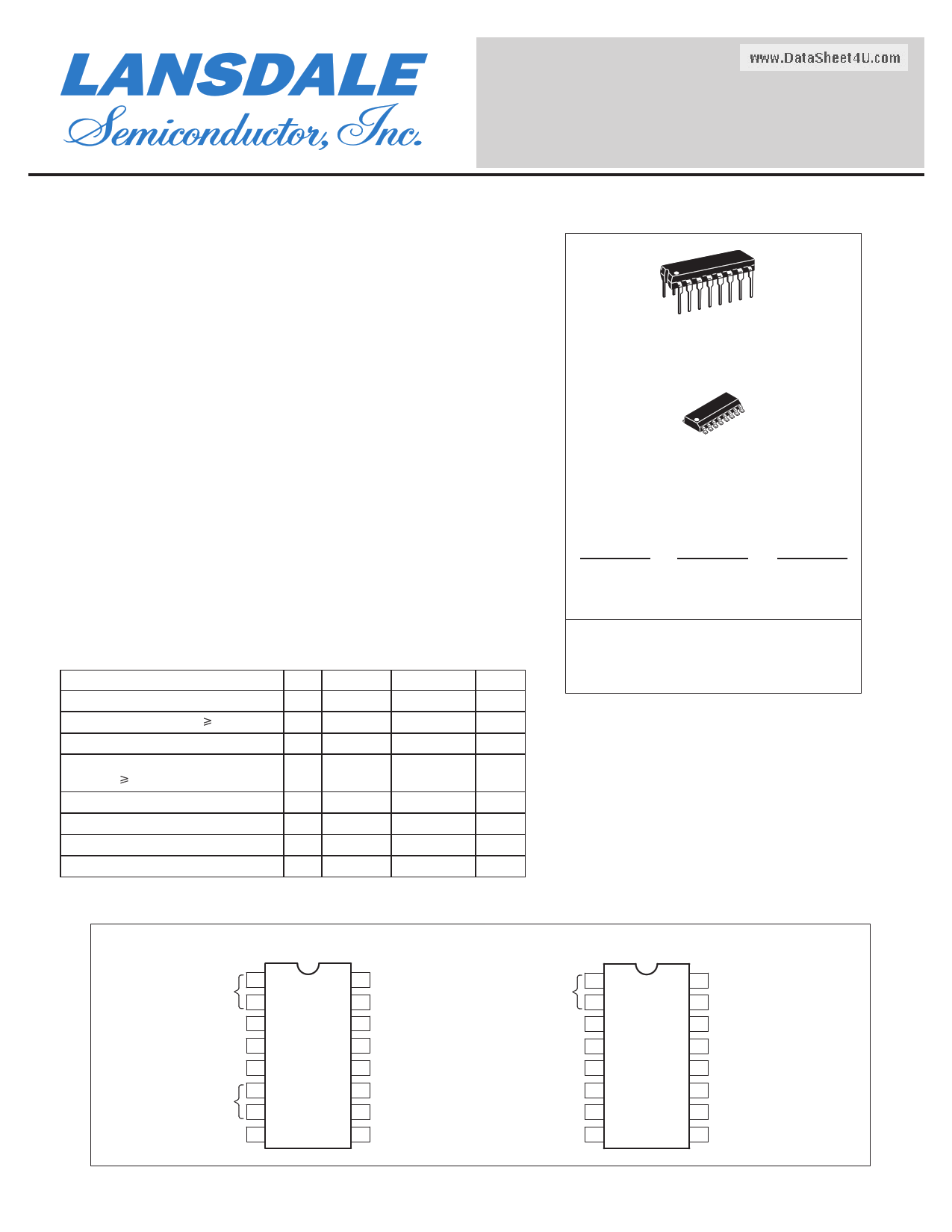
16
1
P DIP 16 = EP
PLASTIC PACKAGE
CASE 648
16
1
SO 16 = -5P
PLASTIC PACKAGE
CASE 751B
(SO–16)
CROSS REFERENCE/ORDERING INFORMATION
PACKAGE
MOTOROLA
LANSDALE
P DIP 16
SO 16
P DIP 16
SO 16
MC3371P
MC3371D
MC3372P
MC3372D
ML3371EP
ML3371-5P
ML3372EP
ML3372-5P
Note: Lansdale lead free (Pb) product, as it
becomes available, will be identified by a part
number prefix change from ML to MLE.
PIN CONNECTIONS
Crystal Osc
1
2
Mixer Output 3
VCC 4
Limiter Input 5
Decoupling
6
7
Quad Coil 8
ML3371
(Top View)
16 Mixer Input
15 Gnd
14 Mute
13 Meter Drive
12 Squelch Input
11 Filter Output
10 Filter Input
9 Recovered Audio
Crystal Osc
1
2
Mixer Output 3
VCC 4
Limiter Input 5
Decoupling 6
Limiter Output 7
Quad Input 8
ML3372
(Top View)
16 Mixer Input
15 Gnd
14 Mute
13 Meter Drive
12 Squelch Input
11 Filter Output
10 Filter Input
9 Recovered Audio
Page 1 of 19
www.lansdale.com
Issue A
1 page 
ML3371, ML3372
LANSDALE Semiconductor, Inc.
TYPICAL CURVES
(Unmatched Input)
Figure 3. Total Harmonic Distortion
versus Temperature
5.0
VCC = 4.0 Vdc
4.0 RF Input = –30 dBm
fo = 10.7 MHz
3.0
2.0
1.0
0
–55 –35 –15 5.0 25 45 65 85
TA, AMBIENT TEMPERATURE (°C)
105 125
Figure 4. RSSI versus RF Input
70
TA = 75°C
60
50 TA = –30°C
40 TA = 25°C
30
20
10 TA = 75°C
0
–140 –120 –100
VCC = 4.0 Vdc
fo = 10.7 MHz
TA = –30°C
–80 –60 –40
RF INPUT (dBm)
–20
0
20
Figure 5. RSSI Output versus Temperature
60
54 –30 dBm
48
42
VCC = 4.0 Vdc
fo = 10.7 MHz
36
30
24 –70 dBm
18
12
6.0 –110 dBm
www.DataSh0eet4U.com
–55 –35 –15 5.0 25 45 65 85
TA, AMBIENT TEMPERATURE (°C)
105 125
Figure 6. Mixer Output versus RF Input
0
–10
100 MHz
Desired Products
–20
–30
100 MHz
3rd Order Products
–40
–50
–60
VCC = 4.0 Vdc
TA = 27°C
–70
– 70 – 60 – 50 – 40 – 30 – 20 – 10
0 10
RF INPUT (dBm)
Figure 7. Mixer Gain versus Supply Voltage
30
27 TA = 75°C
24
21
TA = –30°C
TA = 25°C
18
15
12
9.0 fo = 10.7 MHz
6.0
RFin –40 dBm
1.8 kΩ Load
3.0
0
0 1.0 2.0 3.0 4.0 5.0 6.0 7.0 8.0 9.0 10
VCC, SUPPLY VOLTAGE (V)
Figure 8. Mixer Gain versus Frequency
40
VCC = 4.0 Vdc
TA = 27°C
30 RFin = –40 dBm
20
10
0
1.0
–10 dBm
–15 dBm
–20 dBm
10 100
f, FREQUENCY (MHz)
5.0 dBm
0 dBm
–5.0 dBm
1000
Page 5 of 19
www.lansdale.com
Issue A
5 Page 
ML3371, ML3372
LANSDALE Semiconductor, Inc.
CIRCUIT DESCRIPTION
The ML3371 and ML3372 are low power narrowband FM
receivers with an operating frequency of up to 60 MHz. Its low
voltage design provides low power drain, excellent sensitivity,
and good image rejection in narrowband voice and data link
applications.
This part combines a mixer, an IF (intermediate frequency)
limiter with a logarithmic response signal strength indicator, a
quadrature detector, an active filter and a squelch trigger cir-
cuit. In a typical application, the mixer amplifier converts an
RF input signal to a 455 kHz IF signal. Passing through an
external bandpass filter, the IF signal is fed into a limiting
amplifier and detection circuit where the audio signal is recov-
ered. A conventional quadrature detector is used.
The absence of an input signal is indicated by the presence of
noise above the desired audio frequencies. This “noise band” is
monitored by an active filter and a detector. A squelch switch is
used to mute the audio when noise or a tone is present. The
input signal level is monitored by a meter drive circuit which
detects the amount of IF signal in the limiting amplifier.
LEGACY APPLICATIONS INFORMATION
The oscillator is an internally biased Colpitts type with the
collector, base, and emitter connections at Pins 4, 1 and 2
respectively. This oscillator can be run under crystal control.
For fundamental mode crystals use crystal characterized paral-
lel resonant for 32 pF load. For higher frequencies, use 3rd
overtone series mode type crystals. The coil (L2) and resistor
RD (R13) are needed to ensure proper and stable operation at
the LO frequency (see Figure 13, 45 MHz application circuit).
The mixer is doubly balanced to reduce spurious radiation.
Conversion gain stated in the AC Electrical Characteristic sta-
ble is typically 20 dB. This power gain measurement was made
under stable conditions using a 50 Ω source at the input and an
external load provided by a 455 kHz ceramic filter at the mixer
ouwtpwuwt.DwahtaiSchheeist4cUo.cnonmected to the VCC (Pin 4) and IF input
(Pin 5). The filter impedance closely matches the1.8 kΩ inter-
nal load resistance at Pin 3 (mixer output). Since the input
impedance at Pin 16 is strongly influenced by a 3.3 kΩ inter-
nal biasing resistor and has a low capacitance, the useful gain
is actually much higher than shown by the standard power gain
measurement. The Smith Chart plot in Figure 17 shows the
measured mixer input impedance versus input frequency with
the mixer input matched to a 50Ω source impedance at the
given frequencies. In order to assure stable operation under
matched conditions, it is necessary to provide a shunt resistor
to ground. Figures 11, 12 and 13 show the input networks used
to derive the mixer input impedance data.
Following the mixer, a ceramic bandpass filter is recom-
mended for IF filtering (i.e. 455 kHz types having a bandwidth
of ±2.0 kHz to ±15 kHz with an input and output impedance
from 1.5 kΩ to 2.0 kΩ). The 6 stage limiting IF amplifier has
approximately 92 dB of gain. The MC3371 and MC3372 are
different in the limiter and quadrature detector circuits. The
MC3371 has a 1.8 kΩ and a 51 kΩ resistor providing internal
dc biasing and the output of the limiter is internally connected,
both directly and through a 10 pF capacitor to the quadrature
detector; whereas, in the MC3372 these components are not
provided internally. Thus, in the MC3371, no external compo-
nents are necessary to match the 455 kHz ceramic filter, while
in the MC3372, external 1.8 kΩ and 51 kΩ biasing resistors
are needed between Pins 5 and 7, respectively (see Figures 12
and 13).
In the MC3371, a parallel LCR quadrature tank circuit is
connected externally from Pin 8 to VCC (similar to the
MC3361). In the MC3372, a quadrature capacitor is needed
externally from Pin 7 to Pin 8 and a parallel LC or a ceramic
discriminator with a damping resistor is also needed from Pin
8 to VCC (similar to the MC3357). The above external quadra-
ture circuitry provides 90° phase shift at the IF center frequen-
cy and enables recovered audio.
The damping resistor determines the peak separation of the
detector and is somewhat critical. As the resistor is decreased, the
separation and the bandwidth is increased but the recovered
audio is decreased. Receiver sensitivity is dependent on the value
of this resistor and the bandwidth ofthe 455 kHz ceramic filter.
On the chip the composite recovered audio, consisting of
carrier component and modulating signal, is passed through a
low pass filter amplifier to reduce the carrier component and
then is fed to Pin 9 which has an output impedance of 450Ω.
The signal still requires further filtering to eliminate the carrier
component, deemphasis, volume control, and further amplifi-
cation before driving a loudspeaker. The relative level of the
composite recovered audio signal at Pin 9 should be consid-
ered for proper interaction with an audio post amplifier and a
given load element. The MC13060 is recommended as a low
power audio amplifier.
The meter output indicates the strength of the IF level and
the output current is proportional to the logarithm of the IF
input signal amplitude. A maximum source current of 60 µA is
available and can be used to drive a meter and to detect a carri-
er presence. This is referred to as a Received Strength Signal
Indicator (RSSI). The output at Pin 13 provides a current
source. Thus, a resistor to ground yields a voltage proportional
to the input carrier signal level. The value of this resistor is
estimated by (VCC(Vdc) – 1.0 V)/60 µA; so for VCC = 4.0
Vdc, the resistor is approximately 50 kΩ and provides a maxi-
mum voltage swing of about 3.0 V.
A simple inverting op amp has an output at Pin 11 and the
inverting input at Pin 10. The noninverting input is connected
to 2.5 V. The op amp may be used as a noise triggered squelch
or as an active noise filter. The bandpass filter is designed with
external impedance elements to discriminate between frequen-
cies. With an external AM detector, the filtered audio signal is
checked for a tone signal or for the presence of noise above the
normal audio band. This information is applied to Pin 12.
Page 11 of 19
www.lansdale.com
Issue A
11 Page | ||
| Páginas | Total 19 Páginas | |
| PDF Descargar | [ Datasheet MC3371.PDF ] | |
Hoja de datos destacado
| Número de pieza | Descripción | Fabricantes |
| MC33702 | Microprocessor Power Supply | Motorola Semiconductors |
| MC3370P | Zero Voltage Switch | Motorola Semiconductors |
| MC3371 | (MC3372) LOW POWER FM IF | Motorola Semiconductors |
| MC3371 | (MC3371 / MC3372) Low Power Narrowband FM IF | LANSDALE Semiconductor |
| Número de pieza | Descripción | Fabricantes |
| SLA6805M | High Voltage 3 phase Motor Driver IC. |
Sanken |
| SDC1742 | 12- and 14-Bit Hybrid Synchro / Resolver-to-Digital Converters. |
Analog Devices |
|
DataSheet.es es una pagina web que funciona como un repositorio de manuales o hoja de datos de muchos de los productos más populares, |
| DataSheet.es | 2020 | Privacy Policy | Contacto | Buscar |