|
|
|
PDF AUIRF7665S2TR1 Data sheet ( Hoja de datos )
| Número de pieza | AUIRF7665S2TR1 | |
| Descripción | N-Channel HEXFET Power MOSFET | |
| Fabricantes | International Rectifier | |
| Logotipo | ||
Hay una vista previa y un enlace de descarga de AUIRF7665S2TR1 (archivo pdf) en la parte inferior de esta página. Total 11 Páginas | ||
|
No Preview Available !
AUTOMOTIVE GRADE
PD - 96286
AUIRF7665S2TR
AUIRF7665S2TR1
• Advanced Process Technology
• Optimized for Class D Audio Amplifier Applications
• Low Rds(on) for Improved Efficiency
• Low Qg for Better THD and Improved Efficiency
• Low Qrr for Better THD and Lower EMI
• Low Parasitic Inductance for Reduced Ringing and Lower EMI
• Delivers up to 100W per Channel into 8Ω with No Heatsink
• Dual Sided Cooling
• 175°C Operating Temperature
• Repetitive Avalanche Capability for Robustness and Reliability
• Lead free, RoHS and Halogen free
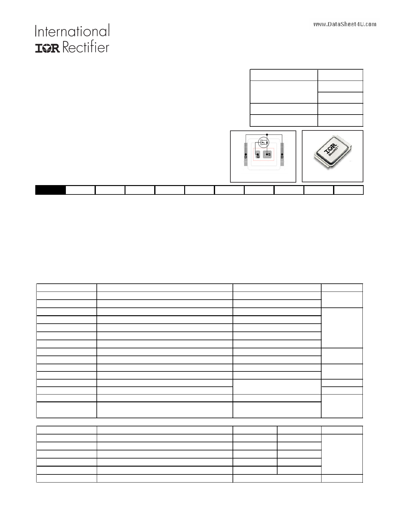
DirectFET Power MOSFET
V(BR)DSS
RDS(on) typ.
100V
51mΩ
max.
RG (typical)
Qg (typical)
62mΩ
3.5Ω
8.3nC
Applicable DirectFET Outline and Substrate Outline
SB DirectFET ISOMETRIC
SB SC
M2 M4
L4 L6 L8
Description
The AUIRF7665S2TR/TR1 combines the latest Automotive HEXFET® Power MOSFET Silicon technology with the advanced DirectFET
packaging platform to produce a best in class part for Automotive Class D audio amplifier applications. The DirectFET package is compatible
with existing layout geometries used in power applications, PCB assembly equipment and vapor phase, infra-red or convection soldering
techniques, when application note AN-1035 is followed regarding the manufacturing methods and processes. The DirectFET package
allows dual sided cooling to maximize thermal transfer in automotive power systems.
This HEXFET Power MOSFET optimizes gate charge, body diode reverse recovery and internal gate resistance to improve key Class D
audio amplifier performance factors such as efficiency, THD and EMI. Moreover the DirectFET packaging platform offers low parasitic
inductance and resistance when compared to conventional wire bonded SOIC packages which improves EMI performance by reducing the
voltage ringing that accompanies current transients.
These features combine to make this MOSFET a highly desirable component in Automotive Class D audio amplifier systems.
Absolute Maximum Ratings
Parameter
Max.
Units
VDS Drain-to-Source Voltage
VGS Gate-to-Source Voltage
www.DaItDaS@heTeCt4=U2.c5o°mC
ID @ TC = 100°C
ID @ TA = 25°C
fContinuous Drain Current, VGS @ 10V (Silicon Limited)
fContinuous Drain Current, VGS @ 10V (Silicon Limited)
eContinuous Drain Current, VGS @ 10V (Silicon Limited)
ID @ TC = 25°C
IDM
PD @TC = 25°C
PD @TA = 25°C
EAS
EAS(tested)
IAR
EAR
TP
Continuous Drain Current, VGS @ 10V (Package Limited)
fPulsed Drain Current
fPower Dissipation
ePower Dissipation
hSingle Pulse Avalanche Energy (Thermally Limited)
hSingle Pulse Avalanche Energy (Tested Value)
ÃgAvalanche Current
gRepetitive Avalanche Energy
Peak Soldering Temperature
TJ Operating Junction and
TSTG
Storage Temperature Range
Thermal Resistance
100
± 20
14.4
10.2
4.1
77
58
30
2.4
37
56
See Fig. 18a,18b,16,17
270
-55 to + 175
V
A
W
mJ
A
mJ
°C
RθJA
RθJA
RθJA
RθJ-Can
RθJ-PCB
Parameter
eJunction-to-Ambient
jJunction-to-Ambient
kJunction-to-Ambient
flJunction-to-Can
Junction-to-PCB Mounted
fLinear Derating Factor
Typ.
Max.
––– 63
12.5 –––
20 –––
––– 5.0
1.4 –––
0.2
Units
°C/W
W/°C
HEXFET® is a registered trademark of International Rectifier.
www.irf.com
1
01/05/10
1 page 
AUIRF7665S2TR/TR1
100
6.5 TJ = -40°C
TJ = 25°C
TJ = 175°C
5.5 10
4.5
1
3.5
ID = 25µA
ID = 250µA
2.5 ID = 1.0mA
D = 1.0A
1.5
-75 -50 -25 0 25 50 75 100 125 150 175
TJ , Temperature ( °C )
Fig 7. Typical Threshold Voltage vs. Junction Temperature
0.1
VGS = 0V
0.01
0.1 0.2 0.3 0.4 0.5 0.6 0.7 0.8 0.9 1.0 1.1 1.2
VSD, Source-to-Drain Voltage (V)
Fig 8. Typical Source-Drain Diode Forward Voltage
20
18 TJ = 25°C
16
10000
VGS = 0V, f = 1 MHZ
Ciss = C gs + Cgd, C ds SHORTED
Crss = Cgd
Coss = Cds + Cgd
14
1000
12 Ciss
10 TJ = 175°C
8 Coss
6 100
4 VDS = 10V
2 380µs PULSE WIDTH
Crss
0
www.DataSheet4U0.com2 4 6 8 10 12 14 16
ID,Drain-to-Source Current (A)
18
10
1
10
VDS, Drain-to-Source Voltage (V)
100
Fig 9. Typical Forward Transconductance Vs. Drain Current
Fig 10. Typical Capacitance vs.Drain-to-Source Voltage
14.0
12.0
10.0
8.0
ID= 8.9A
VDS= 80V
VDS= 50V
VDS= 20V
6.0
4.0
16
14
12
10
8
6
4
2.0 2
0.0
0
2 4 6 8 10
QG, Total Gate Charge (nC)
12
0
25
50 75 100 125 150
TC , Case Temperature (°C)
175
Fig.11 Typical Gate Charge vs.Gate-to-Source Voltage
www.irf.com
Fig 12. Maximum Drain Current vs. Case Temperature
5
5 Page 
AUIRF7665S2TR/TR1
Notes:
Click on this section to link to the appropriate technical paper.
Click on this section to link to the DirectFET Website.
Starting TJ = 25°C, L = 0.944mH, RG = 25Ω, IAS = 8.9A.
Pulse width ≤ 400µs; duty cycle ≤ 2%.
Used double sided cooling, mounting pad with large heatsink.
Surface mounted on 1 in. square Cu board, steady state.
Mounted on minimum footprint full size board with metalized
TC measured with thermocouple mounted to top (Drain) of part.
back and with small clip heatsink.
Repetitive rating; pulse width limited by max. junction temperature. Rθ is measured at TJ of approximately 90°C.
IMPORTANT NOTICE
Unless specifically designated for the automotive market, International Rectifier Corporation and its subsidiaries (IR) reserve the
right to make corrections, modifications, enhancements, improvements, and other changes to its products and services at any time
and to discontinue any product or services without notice. Part numbers designated with the “AU” prefix follow automotive industry
and / or customer specific requirements with regards to product discontinuance and process change notification. All products are
sold subject to IR’s terms and conditions of sale supplied at the time of order acknowledgment.
IR warrants performance of its hardware products to the specifications applicable at the time of sale in accordance with IR’s standard
warranty. Testing and other quality control techniques are used to the extent IR deems necessary to support this warranty. Except
where mandated by government requirements, testing of all parameters of each product is not necessarily performed.
IR assumes no liability for applications assistance or customer product design. Customers are responsible for their products and
applications using IR components. To minimize the risks with customer products and applications, customers should provide ad-
equate design and operating safeguards.
Reproduction of IR information in IR data books or data sheets is permissible only if reproduction is without alteration and is
accompanied by all associated warranties, conditions, limitations, and notices. Reproduction of this information with alterations is
an unfair and deceptive business practice. IR is not responsible or liable for such altered documentation. Information of third parties
may be subject to additional restrictions.
Resale of IR products or serviced with statements different from or beyond the parameters stated by IR for that product or service
voids all express and any implied warranties for the associated IR product or service and is an unfair and deceptive business
practice. IR is not responsible or liable for any such statements.
IR products are not designed, intended, or authorized for use as components in systems intended for surgical implant into the body,
or in other applications intended to support or sustain life, or in any other application in which the failure of the IR product could
www.DacrtaeSahteeeat4sUitu.caotmion where personal injury or death may occur. Should Buyer purchase or use IR products for any such unintended or
unauthorized application, Buyer shall indemnify and hold International Rectifier and its officers, employees, subsidiaries, affiliates,
and distributors harmless against all claims, costs, damages, and expenses, and reasonable attorney fees arising out of, directly or
indirectly, any claim of personal injury or death associated with such unintended or unauthorized use, even if such claim alleges that
IR was negligent regarding the design or manufacture of the product.
IR products are neither designed nor intended for use in military/aerospace applications or environments unless the IR products are
specifically designated by IR as military-grade or “enhanced plastic.” Only products designated by IR as military-grade meet military
specifications. Buyers acknowledge and agree that any such use of IR products which IR has not designated as military-grade is
solely at the Buyer’s risk, and that they are solely responsible for compliance with all legal and regulatory requirements in connection
with such use.
IR products are neither designed nor intended for use in automotive applications or environments unless the specific IR products are
designated by IR as compliant with ISO/TS 16949 requirements and bear a part number including the designation “AU”. Buyers
acknowledge and agree that, if they use any non-designated products in automotive applications, IR will not be responsible for any
failure to meet such requirements
For technical support, please contact IR’s Technical Assistance Center
http://www.irf.com/technical-info/
www.irf.com
WORLD HEADQUARTERS:
233 Kansas St., El Segundo, California 90245
Tel: (310) 252-7105
11
11 Page | ||
| Páginas | Total 11 Páginas | |
| PDF Descargar | [ Datasheet AUIRF7665S2TR1.PDF ] | |
Hoja de datos destacado
| Número de pieza | Descripción | Fabricantes |
| AUIRF7665S2TR | N-Channel HEXFET Power MOSFET | International Rectifier |
| AUIRF7665S2TR | Power MOSFET ( Transistor ) | Infineon |
| AUIRF7665S2TR1 | N-Channel HEXFET Power MOSFET | International Rectifier |
| Número de pieza | Descripción | Fabricantes |
| SLA6805M | High Voltage 3 phase Motor Driver IC. |
Sanken |
| SDC1742 | 12- and 14-Bit Hybrid Synchro / Resolver-to-Digital Converters. |
Analog Devices |
|
DataSheet.es es una pagina web que funciona como un repositorio de manuales o hoja de datos de muchos de los productos más populares, |
| DataSheet.es | 2020 | Privacy Policy | Contacto | Buscar |