|
|
|
PDF ATR4252 Data sheet ( Hoja de datos )
| Número de pieza | ATR4252 | |
| Descripción | All-in-One IC Solution | |
| Fabricantes | ATMEL Corporation | |
| Logotipo | ||
Hay una vista previa y un enlace de descarga de ATR4252 (archivo pdf) en la parte inferior de esta página. Total 10 Páginas | ||
|
No Preview Available !
Features
• Highly Integrated - All-in-one Active Antenna IC
• Integrated AGC for AM and FM
• Integrated Driver for AM and FM PIN Diodes
• Integrated Power Supply Regulator
• Integrated Antenna Sensor
• Separated AM LNA, AM Buffer and FM Amplifier
• High Dynamic Range for AM and FM
• Excellent Noise Performance
• High Intercept Point 3rd Order for FM
• FM Amplifier Adjustable to Various Cable Impedances
• High Intercept Point 2nd and 3rd Order for AM
• Low Noise Output Voltage
• Low Power Consumption
• Low Output Impedance AM
• Only Small Capacitor Values Necessary at AM AGC
• Large AM Frequency Range to Cover DRM Broadcast Signals
1. Description
The ATR4252 is a highly integrated high performance AM/FM antenna amplification
IC with several features. The device has built-in AGC's for both AM and FM, antenna
detection, a power supply regulator as well as additional pre-integrated peripherals.
The ATR4252 is based on BICMOS technology. The device is designed in particular
for car application and is suitable for active antennas located in several positions on
the car such as bumpers, windscreen, mirrors or windows.
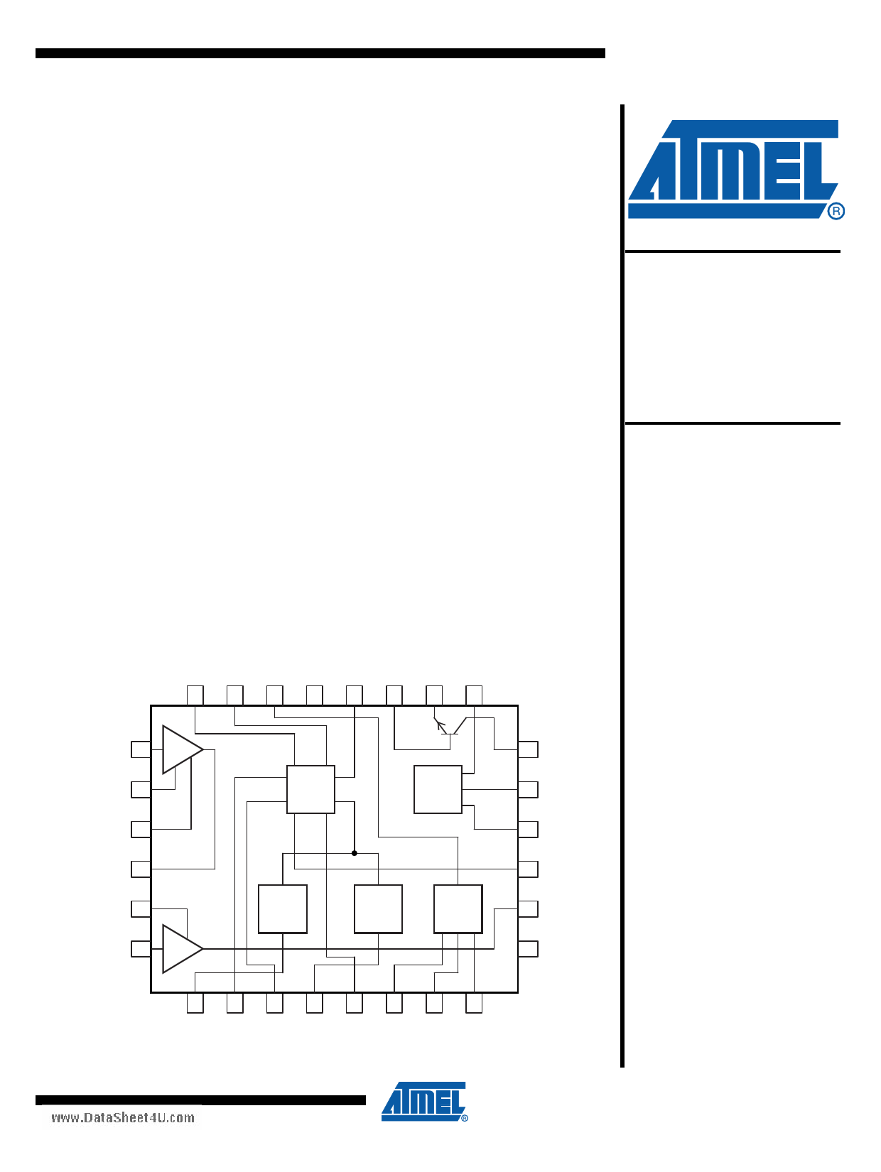
Figure 1-1.
Block Diagram
AM LNA
FM
BIAS REF AMPD GND2 BIAS
22 21 20 19 18
FMB
17
FME FMPD
16 15
AM LNA IN 23
AM
LNA
AM LNA
SOURCE
24
CASCODE
FILTER
25
Voltage
Supply
FM
Amplifier
AGC
(FM)
14 FMC
13 FMDET
12 FMTC
AM LNA OUT 26
11 VS
AMBIAS 27
AMBUF IN 28
AM
Buffer
Antenna
Detect
Over
Voltage
AGC
(AM)
10 AMOUT
9 GND1
12345678
ANTENNA VS VSTART OVDET VREGO AMTC1 AMTC2 AMDET
SENSE FILTER
www.DataSheet4U.com
All-in-One IC
Solution for
Active
Antennas
ATR4252
Summary
Preliminary
NOTE: This is a summary document.
The complete document is available
under NDA. For more information,
please contact your local Atmel sales
office.
9154AS–AUDR–09/09
1 page 
ATR4252 [Preliminary]
www.DataSheet4U.com
The AM buffer amplifier has a very low input capacitance of typically 2.45 pF and can also be
connected directly to the car antenna if no additional gain is required. Due to the low output
impedance of 8Ω, the buffer amplifier is perfectly suited to drive the capacitive load of long
antenna cables. The voltage gain of this amplifier is close to 1 (0 dB), but the insertion gain that
is achieved when the buffer amplifier is inserted between antenna output and antenna cable
may be much higher (up to 35 dB). The actual value, of course, depends on antenna and cable
capacitances.
The input of the buffer amplifier is connected by an external 4.7 MΩ resistor to the bias voltage in
order to maintain high input impedance and low noise voltage.
AM tuners in car radios usually use PIN diode attenuators at their input. These PIN diode atten-
uators attenuate the signal by reducing the input impedance of the tuner. Therefore, a series
resistor is used at the AM amplifier output in the standard application. This series resistor guar-
antees well-defined source impedance for the radio tuner and protects the output of the AM
amplifier from short circuit by the PIN diode attenuator in the car radio.
3.2 AM AGC
The IC is equipped with an AM AGC capability to prevent overdriving of the amplifier in case the
amplifier operates near strong signal sources, e.g., transmitters.
The AM amplifier output AMOUT is applied to a resistive voltage divider. This divided signal
feeds the AGC level detector input pin AMDET. The rectified signal is compared against an inter-
nal reference. The threshold of the AGC can be adjusted by modification of the divider ratio of
the external voltage divider. If the threshold is reached ,the pin AMPD opens an internal transis-
tor, which controls the pin diode current and limits the antenna signal to prevent an overdriving
of the AM amplifier.
As the AM AGC has to react very slowly, large capacitors are usually needed for this time delay.
To reduce the cost of the external components, a current control for the time delay is integrated,
so that only small external capacitor values are needed.
The necessary driver for the external pin diode is already incorporated in the ATR4252 IC, which
reduces the BOM cost and the application size.
3.3 FM Amplifier
The FM amplifier is realized with a high performance single NPN transistor. This allows the use
of an amplifier configuration, which is optimized for the desired requirements. For low cost appli-
cation, the common emitter configuration provides good performance at reasonable BOM cost.
For high end application, common base configuration with lossless transformer feedback pro-
vides high IP3 and low noise figure at reasonable current consumption. In both configurations,
gain, input and output impedance can be adjusted by modification of external components.
The temperature compensated bias voltage (FMBIAS) for the base of the NPN transistor is
derived from an integrated voltage reference. The bias current of the FM amplifier is defined by
an external resistor.
9154AS–AUDR–09/09
5
5 Page | ||
| Páginas | Total 10 Páginas | |
| PDF Descargar | [ Datasheet ATR4252.PDF ] | |
Hoja de datos destacado
| Número de pieza | Descripción | Fabricantes |
| ATR4251 | High-dynamic-range Antenna Amplifier IC | ATMEL Corporation |
| ATR4252 | All-in-One IC Solution | ATMEL Corporation |
| ATR4255 | AM/FM RECEIVER IC | ATMEL Corporation |
| ATR4256 | Frequency Synthesizer | ATMEL Corporation |
| Número de pieza | Descripción | Fabricantes |
| SLA6805M | High Voltage 3 phase Motor Driver IC. |
Sanken |
| SDC1742 | 12- and 14-Bit Hybrid Synchro / Resolver-to-Digital Converters. |
Analog Devices |
|
DataSheet.es es una pagina web que funciona como un repositorio de manuales o hoja de datos de muchos de los productos más populares, |
| DataSheet.es | 2020 | Privacy Policy | Contacto | Buscar |