|
|
|
PDF CS3511 Data sheet ( Hoja de datos )
| Número de pieza | CS3511 | |
| Descripción | Stereo 10 W High-efficiency Class-D Audio Power Amplifier | |
| Fabricantes | Cirrus Logic | |
| Logotipo | ||
Hay una vista previa y un enlace de descarga de CS3511 (archivo pdf) en la parte inferior de esta página. Total 26 Páginas | ||
|
No Preview Available !
CS3511www.DataSheet4U.com
Stereo 10 W High-efficiency Class-D Audio Power Amplifier
Features
Closed-loop Advanced ΔΣ Architecture
True Spread Spectrum Modulation
Premium Quality Audio Amplification
– 99 dB Dynamic Range - System Level
– 0.025% THD+N @ 5 W - System Level
– -96 dB Channel Separation
Four Selectable Amplifier Gain Settings
Integrated Protection and Automatic Recovery
for Over-current, Under-voltage, and Thermal
Overload
Single-supply Operation (Typ. = 9-12 V)
No Bootstrap Capacitors Required
Low-power Standby Mode
Supports Differential or Single-ended Inputs
Thermally Enhanced 32-pin, 6 x 6 mm QFN
Package Requires No External Heat Sink
Common Applications
Active Speakers
Portable Media Player Docking Stations
Mini/Micro Shelf Systems
Digital Televisions
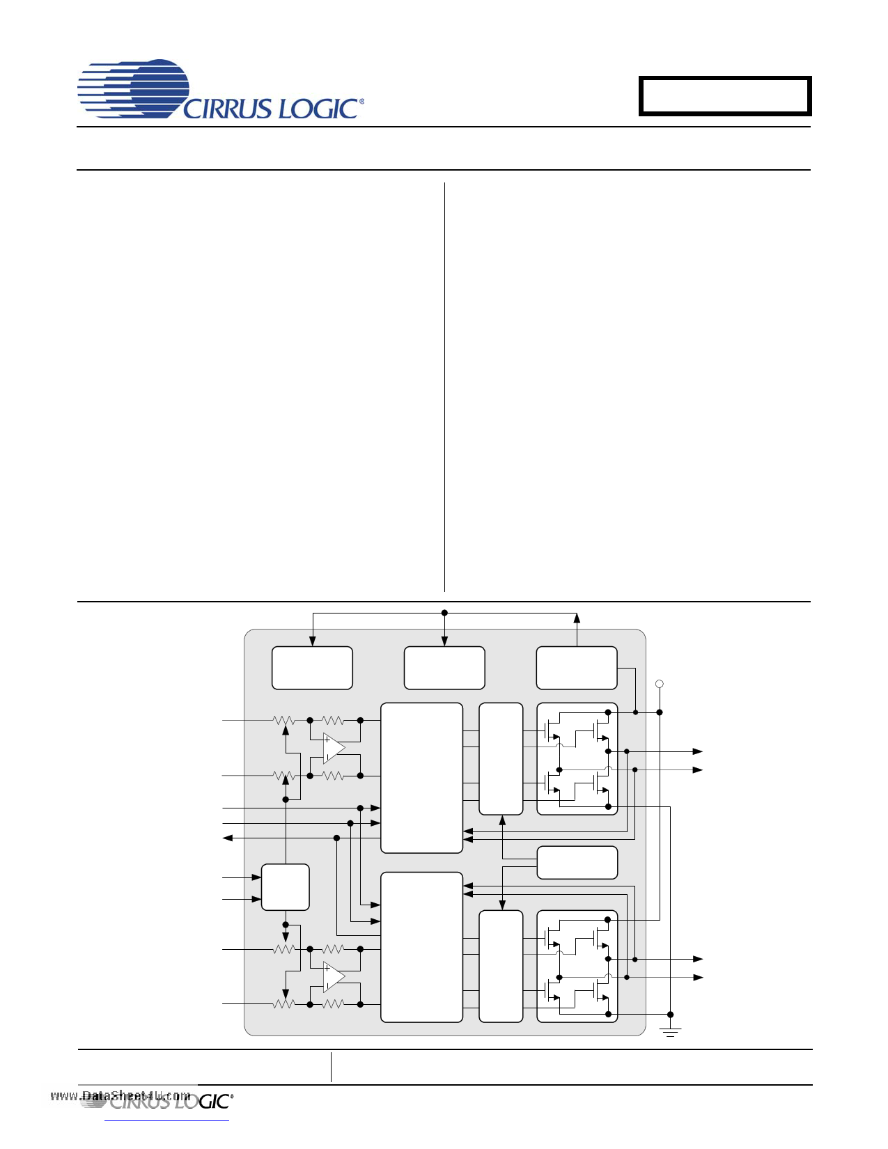
General Description
The CS3511 is a high-efficiency class-D PWM amplifier
that integrates on-chip over-current, under-voltage,
over-temperature protection, and error reporting. An on-
board regulator generates a 5 VDC supply used
to power the internal low-voltage analog and digital cir-
cuitry. The low RDS(ON) outputs can source peak cur-
rents up to 2.7 A, deliver high efficiency, allow a small
device package, and lower power supply voltage levels.
The CS3511 is available in a 32-pin QFN package in
Commercial grade (-10°C to +70°C). The CRD3511
customer reference design is also available. Please re-
fer to “Ordering Information” on page 24 for complete
ordering information.
Analog Power
Digital Power
5V
Regulator
12 V
Positive Input
Channel 1
Negative Input
MUTE
SLEEP
STATUS
GAIN0
GAIN1
Positive Input
Channel 2
Negative Input
Gain
Control
Processing
and
Modulation
Gate
Drive
VP
Channel 1
Positive Output
Negative Output
Charge Pump
Processing
and
Modulation
Gate
Drive
Channel 2
Positive Output
Negative Output
PGND
Preliminary Product Information
http://www.cirrus.com
This document contains information for a new product.
Cirrus Logic reserves the right to modify this product without notice.
Copyright Cirrus Logic, Inc. 2009
(All Rights Reserved)
AUG ‘09
DS845PP2
1 page 
OUT1+
OUT1-
OUT2+
OUT2-
VP
PGND
CPUMP
DCAP
5VGEN
AGND
IN2+
IN2-
C2
C1
V5A
BIASCAP
Thermal Pad
CS3511
www.DataSheet4U.com
9
12
16
Differential PWM Output (Output) - Differential PWM Outputs for channel 1 and channel 2.
13
10
15 High Voltage Power (Input) - Supply pins for high current H-bridges.
20
11
14 Power Ground (Input) - High current ground for analog outputs.
17
18 Charge Pump Input (Input) - Input pin for charge pump.
19 Charge Pump Switching Pin (Output) - Free-running 350 kHz square wave between VP and ground.
21
5 Volt Generator (Output) - Regulated 5 VDC source used to supply power to the input section (pins 2
and 28).
23
27 Analog Ground (Input) - Connect all pins together directly at the thermal pad of the CS3511.
30
24
25
Negative Analog Input (Input) - Negative Audio Signal for channel 2 and channel 1, respectively.
26
31
Pop Minimization Capacitor (Input) - External capacitor used to reduce turn on/off pops.
28 Analog Power (Input) - Supply for analog circuitry. Connect to 5VGEN.
29 Analog Input Bias (Input) - Input stage bias voltage.
-
Thermal Pad (Input) - Thermal relief pad for optimized heat dissipation. Connect to PGND. See “QFN
Thermal Pad” on page 16 for more information.
DS845PP2
5
5 Page 
CS3511
www.DataSheet4U.com
System
Control
Logic
Single-Ended
Analog Input
Note(R1=R2)
Important: See (Note 3)
Single-Ended
Analog Input
Note(R3=R4)
R1 1.0 µf
R2 1.0 µf
R3 1.0 µf
R4 1.0 µf
1 µf 10 µf + 10 µf + 1 µf
3 GAIN0
22 GAIN1
7 MUTE
6 SLEEP
8 STATUS
27 AGND
1 IN1+
CS3511
32 IN1-
24 IN2+
25 IN2-
28 V5A
31 C1
26 C2
29 BIASCAP
VP 10
0.1 µf
VP
+
220 uF
OUT1+ 9
OUT1- 12
PGND 11
Full-Bridge
Output Filter
Channel 1
Audio Output
(Note 1)
RL
6 Ω to 8 Ω
VP
30 AGND
(Note 2)
18 CPUMP
1.0 µf
VP
0.1 µf
19 DCAP
20 VP
0.1 µf
21 5VGEN
0.1 µf
23 AGND
2 V5D
5 REF
1 µf
20 KΩ
1%
4 DGND
VP 15
0.1 µf
+
220 uF
OUT2+ 16
OUT2- 13
PGND 14
Full-Bridge
Output Filter
Channel 2
Audio Output
(Note 1)
RL
6 Ω to 8 Ω
PGND 17
1. See Section 4.11 for typical full-bridge output filter.
2. Incorrectly connecting the external charge pump circuitry can result in permanent damage to the device.
3. See Section 4.1 for important information regarding using Single-Ended inputs with the CS3511.
Figure 2. Typical Connection Diagram - Stereo Amplifier with Single-Ended Inputs
DS845PP2
11
11 Page | ||
| Páginas | Total 26 Páginas | |
| PDF Descargar | [ Datasheet CS3511.PDF ] | |
Hoja de datos destacado
| Número de pieza | Descripción | Fabricantes |
| CS3511 | Stereo 10 W High-efficiency Class-D Audio Power Amplifier | Cirrus Logic |
| Número de pieza | Descripción | Fabricantes |
| SLA6805M | High Voltage 3 phase Motor Driver IC. |
Sanken |
| SDC1742 | 12- and 14-Bit Hybrid Synchro / Resolver-to-Digital Converters. |
Analog Devices |
|
DataSheet.es es una pagina web que funciona como un repositorio de manuales o hoja de datos de muchos de los productos más populares, |
| DataSheet.es | 2020 | Privacy Policy | Contacto | Buscar |