|
|
|
PDF AD8642 Data sheet ( Hoja de datos )
| Número de pieza | AD8642 | |
| Descripción | JFET Amplifiers | |
| Fabricantes | Analog Devices | |
| Logotipo | ||
Hay una vista previa y un enlace de descarga de AD8642 (archivo pdf) en la parte inferior de esta página. Total 15 Páginas | ||
|
No Preview Available !
Data Sheet
Low Power, Rail-to-Rail Output, Precision
JFET Amplifiers
AD8641/AD8642/AD8643
FEATURES
Low supply current: 250 μA max
Very low input bias current: 1 pA max
Low offset voltage: 750 μV max
Single-supply operation: 5 V to 26 V
Dual-supply operation: ±2.5 V to ±13 V
Rail-to-rail output
Unity-gain stable
No phase reversal
SC70 package
APPLICATIONS
Line-/battery-powered instruments
Photodiode amplifiers
Precision current sensing
Medical instrumentation
Industrial controls
Precision filters
Portable audio
ATE
GENERAL DESCRIPTION
The AD8641/AD8642/AD8643 are low power, precision JFET
input amplifiers featuring extremely low input bias current and
rail-to-rail output. The ability to swing nearly rail-to-rail at the
input and rail-to-rail at the output enables designers to buffer
complementary metal-oxide semiconductor digital-to-analog
converters (CMOS DACs), ASICs, and other wide output swing
devices in single-supply systems. The outputs remain stable
with capacitive loads of more than 500 pF.
The AD8641/AD8642/AD8643 are suitable for applications
utilizing multichannel boards that require low power to manage
heat. Other applications include photodiodes, ATE reference
level drivers, battery management, and industrial controls.
The AD8641/AD8642/AD8643 are fully specified over the
extended industrial temperature range of −40°C to +125°C. The
AD8641 is available in 5-lead SC70 and 8-lead SOIC lead-free
packages. The AD8642 is available in 8-lead MSOP and 8-lead
SOIC lead-free packages. The AD8643 is available in 14-lead
SOIC and 16-lead, 3 mm × 3 mm, LFCSP lead-free packages.
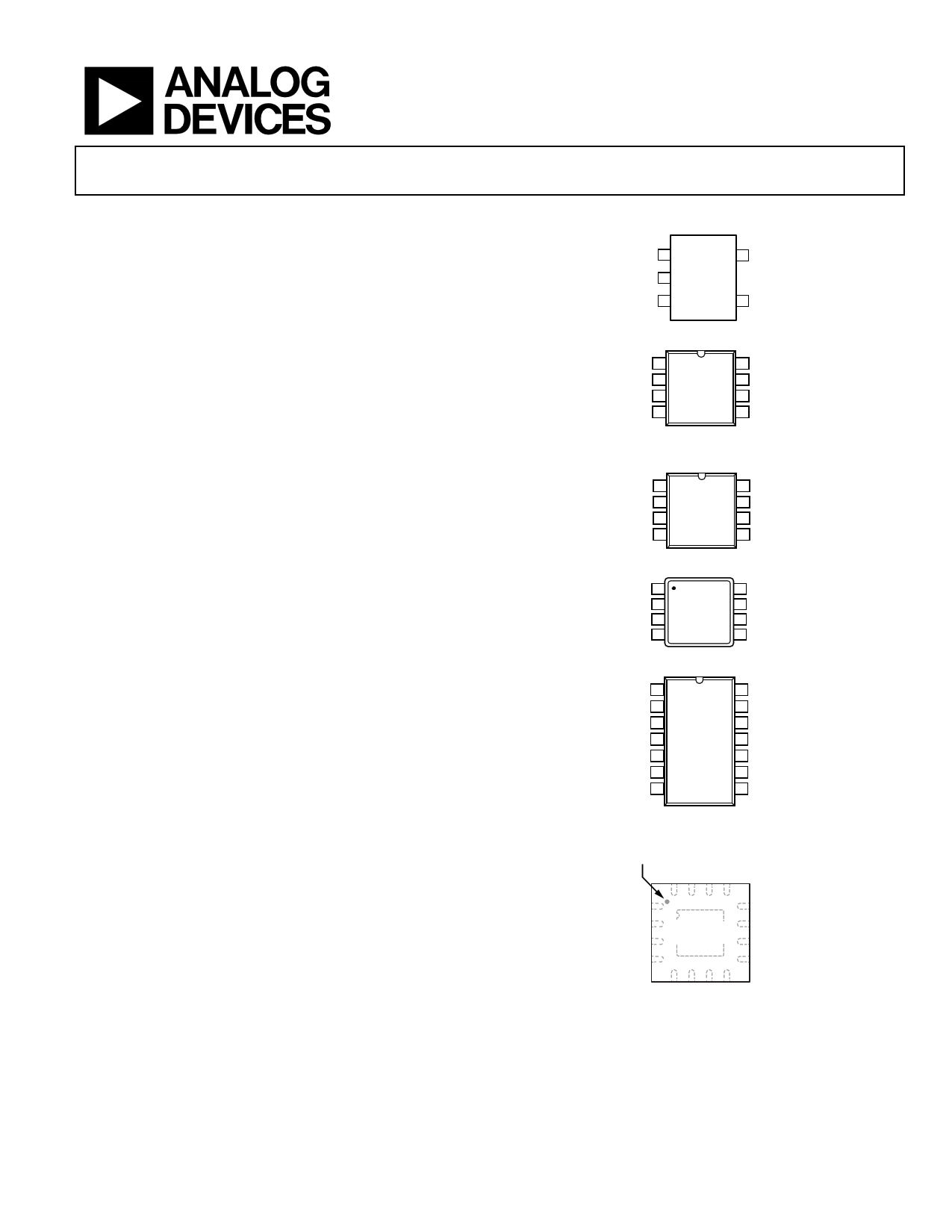
PIN CONFIGURATIONS
OUT 1
5 VCC
AD8641
VEE 2 TOP VIEW
(Not to Scale)
+IN 3
4 –IN
Figure 1. 5-Lead SC70 (KS-5)
NIC 1
8 NIC
–IN 2 AD8641 7 VCC
+IN 3 TOP VIEW 6 OUT
(Not to Scale)
VEE 4
5 NIC
NIC = NO INTERNAL CONNECTION.
Figure 2. 8-Lead SOIC (R-8)
OUT A 1
8 V+
–IN A 2 AD8642 7 OUT B
+IN A 3 TOP VIEW 6 –IN B
(Not to Scale)
V– 4
5 +IN B
Figure 3. 8-Lead SOIC (R-8)
OUT A 1
–IN A 2
+IN A 3
V– 4
AD8642
TOP VIEW
(Not to Scale)
8 V+
7 OUT B
6 –IN B
5 +IN B
Figure 4. 8-Lead MSOP (RM-8)
OUT A 1
14 OUT D
–IN A 2
13 –IN D
+IN A 3 AD8643 12 +IN D
V+ 4 TOP VIEW 11 V–
(Not to Scale)
+IN B 5
10 +IN C
–IN B 6
9 –IN C
OUT B 7
8 OUT C
Figure 5. 14-Lead SOIC (R-14)
PIN 1
INDICATOR
–IN A 1
+IN A 2
V+ 3
+IN B 4
AD8643
TOP VIEW
12 –IN D
11 +IN D
10 V–
9 +IN C
Rev. F
Document Feedback
Information furnished by Analog Devices is believed to be accurate and reliable. However, no
responsibility is assumed by Analog Devices for its use, nor for any infringements of patents or other
rights of third parties that may result from its use. Specifications subject to change without notice. No
license is granted by implication or otherwise under any patent or patent rights of Analog Devices.
Trademarksandregisteredtrademarksarethepropertyoftheirrespectiveowners.
NOTES
1. NIC = NO INTERNAL CONNECTION.
2. EXPOSED PAD SHOULD BE CONNECTED TO V+.
Figure 6. 16-Lead LFCSP (CP-16-27) (Not Drawn to Scale)
One Technology Way, P.O. Box 9106, Norwood, MA 02062-9106, U.S.A.
Tel: 781.329.4700 ©2004–2016 Analog Devices, Inc. All rights reserved.
Technical Support
www.analog.com
1 page 
Data Sheet
ABSOLUTE MAXIMUM RATINGS
Absolute maximum ratings apply at 25°C, unless otherwise noted.
Table 3.
Parameter
Supply Voltage
Input Voltage
Differential Input Voltage
Output Short-Circuit Duration
Storage Temperature Range
KS-5, R-8, RM-8, R-14, CP-16 Packages
Operating Temperature Range
Junction Temperature Range
KS-5, R-8, RM-8, R-14, CP-16 Packages
Lead Temperature (Soldering, 60 sec)
Rating
27.3 V
VS− to VS+
±Supply Voltage
Indefinite
−65°C to +150°C
−40°C to +125°C
−65°C to +150°C
300°C
Stresses at or above those listed under Absolute Maximum
Ratings may cause permanent damage to the product. This is a
stress rating only; functional operation of the product at these
or any other conditions above those indicated in the operational
section of this specification is not implied. Operation beyond
the maximum operating conditions for extended periods may
affect product reliability.
AD8641/AD8642/AD8643
THERMAL RESISTANCE
θJA is specified for the worst-case conditions, that is, a device
soldered in a circuit board for surface-mount packages. This
was measured using a standard 4-layer board. For the LFCSP,
solder the exposed pad to a copper plane, which should be
connected to V+.
Table 4.
Package Type
5-Lead SC70 (KS)
8-Lead SOIC (R)
8-Lead MSOP (RM)
14-Lead SOIC (R)
16-Lead LFCSP (CP)
θJA θJC Unit
430 149 °C/W
121 43
°C/W
142 45
°C/W
110 36
°C/W
81 16 °C/W
ESD CAUTION
Rev. F | Page 5 of 15
5 Page 
Data Sheet
70
VS = ±2.5V
60
RL = 10kΩ
VIN = 100mV p-p
AV = +1
50
40 OS–
30
OS+
20
10
0
1 10 100 1000
CAPACITANCE (pF)
Figure 37. Small Signal Overshoot vs. Load Capacitance
1.0
VS = ±13V
0.8 G = +1M
CH1 p-p = 4.26V
0.6
0.4
0.2
10
–0.2
–0.4
–0.6
–0.8
–1.0
–C5 H1 –14.00V –3 –2 –1
0M1.00s1
VCM (V)
2 A C3H1 4–20.0V5
Figure 38. 0.1 Hz to 10 Hz Noise
1.0
VS = ±2.5V
0.8 G = +1M
CH1 p-p = 4.06V
0.6
0.4
0.2
10
–0.2
–0.4
–0.6
–0.8
–1.0
–C5 H1 –14.00V –3 –2 –1
0M1.00s1
2 A C3H1
VCM (V)
Figure 39. 0.1 Hz to 10 Hz Noise
4–20.0V5
1k
VSY = ±13V
AD8641/AD8642/AD8643
100
10
1
10 100 1k
FREQUENCY (Hz)
Figure 40. Voltage Noise Density
1k
VSY = 5V
10k
100
10
1
10 100 1k 10k
FREQUENCY (Hz)
Figure 41. Voltage Noise Density
0.004
0.001
VSY = ±13V
LOAD = 100kΩ
GAIN = +1
8V p-p INPUT
0.0001
1V p-p INPUT
2V p-p INPUT
4V p-p INPUT
0.00001
0.000001
1
100 1k
FREQUENCY (Hz)
10k 20k
Figure 42. Total Harmonic Distortion + Noise vs. Frequency
Rev. F | Page 11 of 15
11 Page | ||
| Páginas | Total 15 Páginas | |
| PDF Descargar | [ Datasheet AD8642.PDF ] | |
Hoja de datos destacado
| Número de pieza | Descripción | Fabricantes |
| AD8641 | JFET Amplifiers | Analog Devices |
| AD8642 | JFET Amplifiers | Analog Devices |
| AD8643 | JFET Amplifiers | Analog Devices |
| AD8644 | Single and Quad +18 V Operational Amplifiers | Analog Devices |
| Número de pieza | Descripción | Fabricantes |
| SLA6805M | High Voltage 3 phase Motor Driver IC. |
Sanken |
| SDC1742 | 12- and 14-Bit Hybrid Synchro / Resolver-to-Digital Converters. |
Analog Devices |
|
DataSheet.es es una pagina web que funciona como un repositorio de manuales o hoja de datos de muchos de los productos más populares, |
| DataSheet.es | 2020 | Privacy Policy | Contacto | Buscar |