|
|
|
PDF KSZ9021GQ Data sheet ( Hoja de datos )
| Número de pieza | KSZ9021GQ | |
| Descripción | Gigabit Ethernet Transceiver | |
| Fabricantes | Micrel Semiconductor | |
| Logotipo | ||
Hay una vista previa y un enlace de descarga de KSZ9021GQ (archivo pdf) en la parte inferior de esta página. Total 30 Páginas | ||
|
No Preview Available !
KSZ9021GQ
Gigabit Ethernet Transceiver
with GMII / MII Support
General Description
Features
The KSZ9021GQ is a completely integrated triple speed
(10Base-T/100Base-TX/1000Base-T) Ethernet Physical
Layer Transceiver for transmission and reception of data
on standard CAT-5 unshielded twisted pair (UTP) cable.
The KSZ9021GQ provides the industry standard GMII/MII
(Gigabit Media Independent Interface / Media Independent
Interface) for direct connection to GMII/MII MACs in
Gigabit Ethernet Processors and Switches for data transfer
at 1000 Mbps or 10/100 Mbps speed.
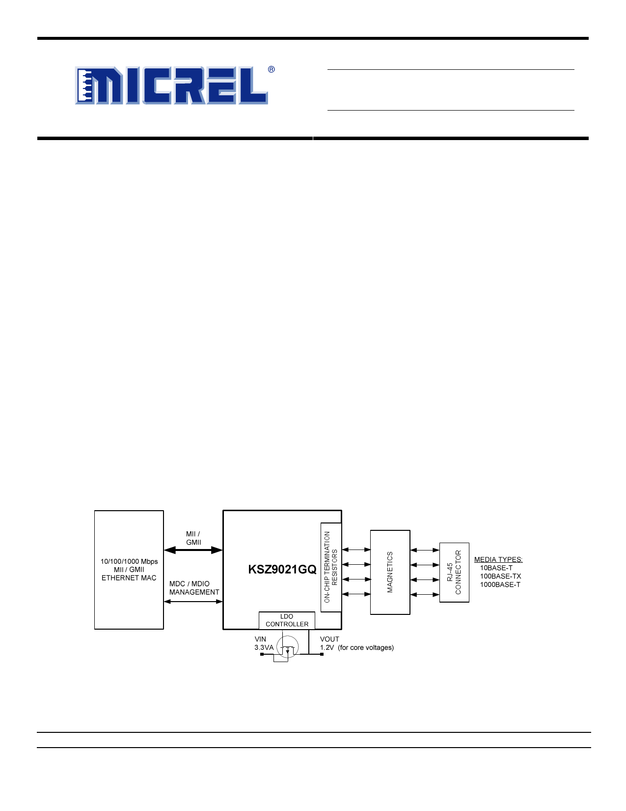
The KSZ9021GQ reduces board cost and simplifies board
layout by using on-chip termination resistors for the four
differential pairs and by integrating a LDO controller to
drive a low cost MOSFET to supply the 1.2V core.
The KSZ9021GQ provides diagnostic features to facilitate
system bring-up and debugging in production testing and
in product deployment. Parametric NAND tree support
enables fault detection between KSZ9021 I/Os and board.
Micrel LinkMD® TDR-based cable diagnostics permit
identification of faulty copper cabling. Remote and local
loopback functions provide verification of analog and
digital data paths.
The KSZ9021GQ is available in a 128-pin, lead-free PQFP
package (See Ordering Information).
• Single-chip 10/100/1000 Mbps IEEE 802.3 compliant
Ethernet Transceiver
• GMII/MII standard compliant interface
• Auto-negotiation to automatically select the highest link
up speed (10/100/100 Mbps) and duplex (half/full)
• On-chip termination resistors for the differential pairs
• On-chip LDO controller to support single 3.3V supply
operation – requires only external FET to generate 1.2V
for the core
• Jumbo frame support up to 16KB
• 125MHz Reference Clock Output
• Programmable LED outputs for link, activity and speed
• Baseline Wander Correction
• LinkMD® TDR-based cable diagnostics for identification
of faulty copper cabling
• Parametric NAND Tree support for fault detection
between chip I/Os and board.
• Loopback modes for diagnostics
• Automatic MDI/MDI-X crossover for detection and
correction of pair swap at all speeds of operation
____________________________________________________________________________________________________________
Functional Diagram
LinkMD is a registered trademark of Micrel, Inc.
Micrel Inc. • 2180 Fortune Drive • San Jose, CA 95131 • USA • tel +1 (408) 944-0800 • fax + 1 (408) 474-1000 • http://www.micrel.com
September 2010
M9999-091010-1.2
1 page 
Micrel, Inc.
KSZ9021GQ
Extended Registers .......................................................................................................................................................... 44
Absolute Maximum Ratings(1) ............................................................................................................................................ 46
Operating Ratings(2) ............................................................................................................................................................ 46
Electrical Characteristics(3) ................................................................................................................................................ 46
Timing Diagrams ................................................................................................................................................................. 49
GMII Transmit Timing ....................................................................................................................................................... 49
GMII Receive Timing ........................................................................................................................................................ 50
MII Transmit Timing .......................................................................................................................................................... 51
MII Receive Timing ........................................................................................................................................................... 52
Auto-Negotiation Timing ................................................................................................................................................... 53
MDC/MDIO Timing ........................................................................................................................................................... 54
Reset Timing..................................................................................................................................................................... 55
Reset Circuit ........................................................................................................................................................................ 55
Reference Circuits – LED Strap-in Pins............................................................................................................................ 56
Reference Clock – Connection & Selection ..................................................................................................................... 57
Magnetics Specification ..................................................................................................................................................... 57
Package Information ........................................................................................................................................................... 58
September 2010
5 M9999-091010-1.2
5 Page 
Micrel, Inc.
Pin Number
38
Pin Name
LED6
39 DVDDL
40 VSS
41 VSS
42 LED5 /
PHYAD4
KSZ9021GQ
Type(1)
I/O
Pin Function
LED Output:
Programmable LED6 Output
The LED6 pin is programmed via register 11h bits [7:6], LED_SEL[1:0], and is
defined as followed:
LED_SEL[1:0] = (1,1)
LED_SEL[1:0] = (0,1)
10Base-T Link
Link off
Link on
// 6-LED Configuration (default)
// 5-LED Configuration
Pin State LED Definition
H OFF
L ON
LED_SEL[1:0] = (1,0)
// 4-LED Configuration
10Base-T – Link / Activity
Link off
Pin State LED Definition
H OFF
Link on
L ON
Activity (RX, TX)
Toggle Blinking
LED_SEL[1:0] = (0,0)
// Reserved – not used
P 1.2V digital VDD
Gnd Digital ground
Gnd Digital ground
I/O LED Output:
Programmable LED5 Output /
Configuration Mode:
The pull-up/pull-down value is latched as PHYADD[4]
during power-up / reset. See “Strapping Options”
section for details.
The LED5 pin is programmed via register 11h bits [7:6], LED_SEL[1:0], and is
defined as followed:
LED_SEL[1:0] = (1,1)
LED_SEL[1:0] = (0,1)
100Base-T Link
Link off
Link on
// 6-LED Configuration (default)
// 5-LED Configuration
Pin State LED Definition
H OFF
L ON
LED_SEL[1:0] = (1,0)
// 4-LED Configuration
100Base-T – Link / Activity Pin State LED Definition
Link off
H OFF
Link on
L ON
Activity (RX, TX)
Toggle Blinking
LED_SEL[1:0] = (0,0)
// Reserved – not used
September 2010
11 M9999-091010-1.2
11 Page | ||
| Páginas | Total 30 Páginas | |
| PDF Descargar | [ Datasheet KSZ9021GQ.PDF ] | |
Hoja de datos destacado
| Número de pieza | Descripción | Fabricantes |
| KSZ9021GN | Gigabit Ethernet Transceiver | Micrel Semiconductor |
| KSZ9021GQ | Gigabit Ethernet Transceiver | Micrel Semiconductor |
| Número de pieza | Descripción | Fabricantes |
| SLA6805M | High Voltage 3 phase Motor Driver IC. |
Sanken |
| SDC1742 | 12- and 14-Bit Hybrid Synchro / Resolver-to-Digital Converters. |
Analog Devices |
|
DataSheet.es es una pagina web que funciona como un repositorio de manuales o hoja de datos de muchos de los productos más populares, |
| DataSheet.es | 2020 | Privacy Policy | Contacto | Buscar |