|
|
|
PDF CS42L73 Data sheet ( Hoja de datos )
| Número de pieza | CS42L73 | |
| Descripción | Ultra Low Power Mobile Audio and Telephony CODEC | |
| Fabricantes | Cirrus Logic | |
| Logotipo | ||
Hay una vista previa y un enlace de descarga de CS42L73 (archivo pdf) en la parte inferior de esta página. Total 30 Páginas | ||
|
No Preview Available !
CS42L73
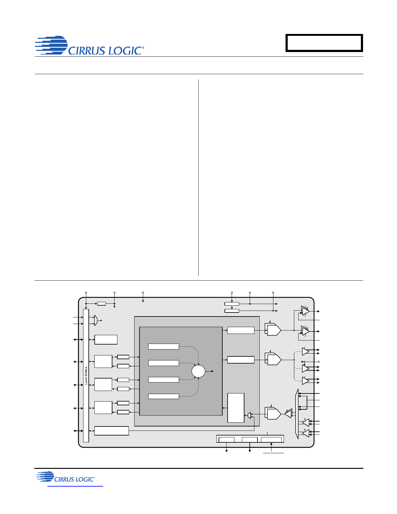
Ultralow Power Mobile Audio and Telephony CODEC
Product Overview
Stereo analog-to-digital converter (ADC)
Dual analog or digital mic support
Dual mic bias generators
Four digital-to-analog converters (DACs)
coupled to five outputs
– Ground-centered stereo headphone amp.
– Ground-centered stereo line output
– Mono ear speaker amplifier
– Mono 1-W speakerphone amplifier
– Mono speakerphone line output for stereo
speakerphone expansion
Three serial ports with asynchronous sample
rate converters
Digital audio mixing and routing
Ultralow Power Consumption
3.8-mW quiescent headphone playback
Applications
Smart phones, ultramobile PCs, and mobile
Internet devices
System Features
Native (no PLL required) support for 6/12/
24 MHz, 13/26 MHz, and 19.2/38.4 MHz
master clock rates and typical audio clock rates
Integrated high-efficiency power management
reduces power consumption
– Internal LDO regulator to reduce internal
digital operating voltage to VL/2 V
– Step-down charge pump provides low
headphone/line out supply voltage
– Inverting charge pump accommodates low
system voltage by providing negative rail for
HP and line amplifier
Flexible speakerphone amplifier powering
– 3.00–5.25 V range
– Independent cycling
Power-down management
– Individual controls for ADCs, digital mic
interface, mic bias generators, serial ports,
and output amplifiers and associated DACs
Programmable thermal overload notification
High-speed I²C™ control port (400 kHz)
(Features continued on page 2)
VL VD_FILT
MCLK1
MCLK2
LDO
VD_FILT
MCLK
Control Port
Auxiliary Serial Port
Audio Serial Port
Voice Serial Port
Digital MIC Interface
Control Port
Auxiliary
Serial Port
SDIN
ASRC
ASRC
SDOUT
Audio
Serial Port
SDIN
ASRC
ASRC
SDOUT
Voice
Serial Port
SDIN
ASRC
ASRC
SDOUT
Digital MIC Interface
VA
VA CS42L73
Digital Processing
Digital Mixer
MIC/Line Input Path
Auxiliary Serial Port
Audio Serial Port
`+
Voice Serial Port
VCP +VCP_FILT -VCP_FILT
Step-Down
Inverting
Volume, Mute, Limiter
Volume, Mute, Limiter
+VCP_FILT
-VCP_FILT
MCLK
Stereo
Multi-bit
DAC
+VCP_FILT
-
+
-VCP_FILT
+VCP_FILT
-
+
-VCP_FILT
MCLK
Stereo
Multi-bit
DAC
VA
B
VP
A
VP
B
Decimator,
HPF,
Noise
Gate,
ALC,
Volume,
Mute,
Swap/Mono
MCLK
Stereo
Multi-bit
ADC
+
-
-6 to +12 dB,
0.5 dB steps
VP
MIC Bias
MIC Bias Short Detect
+10 or
+20 dB
+
-
+
-
+10 or
+20 dB
Headphone Outputs
Pseudo Diff. Input
Line Outputs
Pseudo Diff. Input
+
-
Ear
Speaker
Output
VP
+ Speakerphone Output
- (Left)
+ Speakerphone Line
- Output (Right)
Line Input (Left)
Pseudo Diff. Input
Line Input (Right)
MIC 1
Pseudo Diff. Input
MIC 2
Pseudo Diff. Input
MIC 1 Bias MIC 2 Bias MIC2_SDET
http://www.cirrus.com
Copyright Cirrus Logic, Inc. 2013
(All Rights Reserved)
JULY '13
DS882F1
1 page 
CS42L73
4.11.2 Mixer Input Attenuation Adjustment .................................................................................... 63
4.11.3 Powered-Down Mixer Inputs ............................................................................................... 64
4.11.4 Avoiding Mixer Clipping ....................................................................................................... 64
4.11.5 Mixer Attenuation Values .................................................................................................... 65
4.12 Recommended Operating Procedures ........................................................................................ 65
4.12.1 Initial Power-Up Sequence .................................................................................................. 65
4.12.2 Power-Up Sequence (xSP to HP/LO) ................................................................................. 66
4.12.3 Power-Down Sequence (xSP to HP/LO) ............................................................................. 67
4.12.4 Recommended Sequence for Modification of the MCLK Signal ......................................... 67
4.12.5 Microphone Enabling/Switching Sequence ......................................................................... 68
4.12.6 Final Power-Down Sequence .............................................................................................. 68
4.13 Using MIC2_SDET as Headphone Plug Detect ........................................................................... 69
4.14 Headphone Plug Detect and Mic Short Detect ............................................................................ 70
4.15 Interrupts ...................................................................................................................................... 70
4.16 Control Port Operation ................................................................................................................. 71
4.16.1 I²C Control ........................................................................................................................... 71
4.17 Fast Start Mode ........................................................................................................................... 73
4.18 Headphone High-Impedance Mode ............................................................................................. 75
5. REGISTER QUICK REFERENCE ........................................................................................................ 76
6. REGISTER DESCRIPTION .................................................................................................................. 81
6.1 Fast Mode Enable (Address 00h) .................................................................................................. 81
6.1.1 Test Bits ................................................................................................................................ 81
6.2 Device ID A and B (Address 01h), C and D (Address 02h), and E (Address 03h) (Read Only) . 81
6.2.1 Device I.D. (Read Only) ........................................................................................................ 81
6.3 Revision ID (Address 05h) (Read Only) ......................................................................................... 81
6.3.1 Alpha Revision (Read Only) .................................................................................................. 81
6.3.2 Metal Revision (Read Only) .................................................................................................. 81
6.4 Power Control 1 (Address 06h) ...................................................................................................... 82
6.4.1 Power Down ADC x ............................................................................................................... 82
6.4.2 Power Down Digital Mic x ...................................................................................................... 82
6.4.3 Discharge Filt+ Capacitor ...................................................................................................... 82
6.4.4 Power Down Device .............................................................................................................. 82
6.5 Power Control 2 (Address 07h) ...................................................................................................... 83
6.5.1 Power Down MICx Bias ......................................................................................................... 83
6.5.2 Power Down VSP .................................................................................................................. 83
6.5.3 Power Down ASP SDOUT Path ............................................................................................ 83
6.5.4 Power Down ASP SDIN Path ................................................................................................ 83
6.5.5 Power Down XSP SDOUT Path ............................................................................................ 83
6.5.6 Power Down XSP SDIN Path ................................................................................................ 83
6.6 Power Control 3 and Thermal Overload Threshold Control (Address 08h) ................................... 84
6.6.1 Thermal Overload Threshold Settings ................................................................................... 84
6.6.2 Power Down Thermal Sense ................................................................................................. 84
6.6.3 Power Down Speakerphone Line Output .............................................................................. 84
6.6.4 Power Down Ear Speaker ..................................................................................................... 84
6.6.5 Power Down Speakerphone .................................................................................................. 84
6.6.6 Power Down Line Output ...................................................................................................... 85
6.6.7 Power Down Headphone ...................................................................................................... 85
6.7 Charge Pump Frequency and Class H Configuration (Address 09h) ............................................ 85
6.7.1 Charge Pump Frequency ...................................................................................................... 85
6.7.2 Adaptive Power Adjustment .................................................................................................. 85
6.8 Output Load, Mic Bias, and MIC2 Short Detect Configuration (Address 0Ah) ............................... 86
6.8.1 VP Supply Minimum Voltage Setting ..................................................................................... 86
6.8.2 Speakerphone Light Load Mode Enable ............................................................................... 86
6.8.3 Mic Bias Output Control ........................................................................................................ 86
DS882F1
5
5 Page 
CS42L73
Table 11. Digital Mixer Soft Ramp Rates .................................................................................................. 63
Table 12. Digital Mixer Nonclipping Attenuation Settings ......................................................................... 64
Table 13. Start Up Times .......................................................................................................................... 73
Table 14. Start Up Transition Values ........................................................................................................ 75
Table 15. ASRC Lock Times ................................................................................................................... 130
Table 16. Analog Output Startup Times .................................................................................................. 133
Table 17. WLCSP Package Dimensions ................................................................................................. 135
Table 18. FBGA Package Dimensions .................................................................................................... 136
DS882F1
11
11 Page | ||
| Páginas | Total 30 Páginas | |
| PDF Descargar | [ Datasheet CS42L73.PDF ] | |
Hoja de datos destacado
| Número de pieza | Descripción | Fabricantes |
| CS42L73 | Ultra Low Power Mobile Audio and Telephony CODEC | Cirrus Logic |
| CS42L73 | Ultra Low Power Mobile Audio and Telephony CODEC | Cirrus Logic |
| Número de pieza | Descripción | Fabricantes |
| SLA6805M | High Voltage 3 phase Motor Driver IC. |
Sanken |
| SDC1742 | 12- and 14-Bit Hybrid Synchro / Resolver-to-Digital Converters. |
Analog Devices |
|
DataSheet.es es una pagina web que funciona como un repositorio de manuales o hoja de datos de muchos de los productos más populares, |
| DataSheet.es | 2020 | Privacy Policy | Contacto | Buscar |