|
|
|
PDF AXR3 Data sheet ( Hoja de datos )
| Número de pieza | AXR3 | |
| Descripción | SYSTEM CONNECTORS | |
| Fabricantes | Panasonic | |
| Logotipo | ||
Hay una vista previa y un enlace de descarga de AXR3 (archivo pdf) en la parte inferior de esta página. Total 16 Páginas | ||
|
No Preview Available !
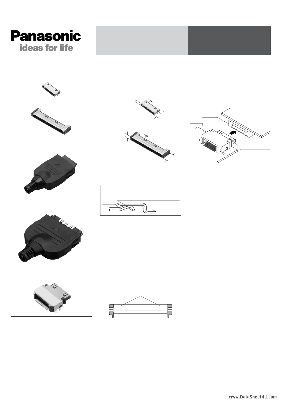
AXR(3/5)
I/O connectors for portable equipment
Receptacle
18, 22, 24 and 26 contacts
50 contacts
System connector ultra low profile type
Plug (cable connection type)
18, 22, 24 and 26 contacts
I/O connectors for portable equipment
Plug (cable connection type)
50 contacts
System connector ultra low profile type
Plug (Board mounting type)
22, 26 and 50 contacts
www.DataSheet4U.com
FOR CELLULAR PHONE; SYSTEM CONNECTORS ULTRA-LOW
ULTRA LOW PROFILE TYPE
PROFILE TYPE (AXR3)
FOR PORTABLE EQUIPMENT I/O CONNECTORS FOR PORTABLE
(0.5mm PITCH)
EQUIPMENT (AXR5)
FEATURES
1. Compact receptacle helps to design
lighter, slimmer, smaller devices.
I/O connector for portable equipment
• 18, 22, 24 and 26 contacts
Ultra low-profile
3.0mm
0.5mm pitch
5. Plugs with 22, 26 and 50 contacts
are also available in board mounting
types. These are ideal for such
applications as the connection
between PDAs and data-
communication cradles.
• 50 contacts
Ultra low-profile
3.5mm
7.2mm
0.5mm pitch
Receptacle
PC board
8.0mm
2. Bellows-type contacts
Our bellows-type contacts resist mating
stress and offer high contact reliability.
Contact
Plug
side
The bellows type contacts are fabricated by
bending thin sheet metal. They offer reliable
contact since a rounded corner, instead of a
sharp edge, is used for tuning fork type contact.
Receptacle
side
3. Coaxial portion with switching
function (1 Form B configuration) can
be applied up to 2GHz.
4. Connection of incorrect pairs is
prevented by cross-manufacturer
mating error prevention key.
By changing the location of the mating
error prevention key, erroneous insertion
of a different connector is prevented. This
eliminates the chance of any problems
that may be caused by mistaken
connections. Please consult us for more
information.
Error prevention key
PC board
Plug
(Board mounting type)
Customizable for several contacts.
Ask about details.
Compliance with RoHS Directive
The key groove is different for every
customer.
Matsushita Electric Works, Ltd.
http://www.mew.co.jp/ac/e/
1 page 
AXR(3/5)
www.DataSheet4U.com
SPECIFICATIONS
1. Characteristics
1) Receptacle–Plug (cable connection type)
Item
Rated
Current
Signal
contact
Battery
contact
Specifications
18 , 22, 24 contacts
26 contacts
50 contacts
0.5 A (1 A can be passed through two terminals connected in series)
(Total for all terminals is max. 10 A.)
2A —
Electrical
characteristics
Contact
resistance
Signal
contact
Battery
contact
Max. 110mΩ (Initial)
Max. 50mΩ (Initial)
—
Insulation resistance
Min. 1,000MΩ (Initial)
Breakdown voltage
150V AC for 1 min.
Mechanical
characteristics
Lifetime
characteristics
Environmental
characteristics
Unit weight
Lever lock strength
Min. 49N {5kgf}
Insertion and removal life
of plug and receptacle
Mechanical life: 10,000 times
Contact resistance after testing:
Max. 110mΩ
Ambient temperature
–35°C to +65°C
Mechanical life:
5,000 times (mechanical
insertion and removal)
Contact resistance after
testing:
Max. 110mΩ
Storage temperature
–40°C to +70°C (The allowable storage temperature is
–40°C to +50°C if unopened from original packaging)
Resistance
to soldering
heat
Receptacle
Reflow soldering: peak temperature 245°C or less
Plug
Hand soldering: Soldering iron temperature 300°C, 5 sec. or less
Receptacle (AXR35371P) 22 contacts: 0.86 g
Plug (AXR30341) 22 contacts: 6.18 g
Receptacle (AXR51508P)
50 contacts: 1.42 g
Plug (AXR5256S)
50 contacts: 11.1 g
Condition
—
Characteristic of receptacle
alone.
Measured based on the
milliohmmeter measurement
method of JIS C 5402, except for
the resistance of the cord on the
plug side.
Measured based on the
milliohmmeter measurement
method of JIS C 5402, except for
the resistance of the terminals
on the battery side.
Using 500V DC megger
(applied for 1 min.)
Rated voltage is applied for one
minute and check for short circuit
or damage with a detection
current of 1 mA.
The plug is pulled off with the
connectors mated.
The connectors are connected
and disconnected at a rate of
200 times/hour or less.
No freezing or condensation in
low temperatures
No freezing or condensation in
low temperatures
Surface temperature (shell) from
infrared reflow soldering
machine
—
—
2) Receptacle–Plug (Board mounting type)
Specifications
Item
22, 26, 50 contacts
Electrical
characteristics
Rated
current
Signal
contact
Contact
Signal
resistance contact
Insulation resistance
0.5 A (7 A can be passed through all terminals connected)
(The total for 50 terminals is max. 10 A.)
22 contacts (A type) Max. 110 mΩ (Initial)
22 contacts (B type) Max. 140 mΩ (Initial)
26 contacts (B type) Max. 110 mΩ (Initial)
50 contacts (B type) Max. 110 mΩ (Initial)
Min. 1,000MΩ (Initial)
Breakdown voltage
150 V AC for 1 min.
Lifetime
characteristics
Insertion and removal life
of plug and receptacle
Mechanical life: 5,000 times
Contact resistance after testing: Max. 110 mΩ
(Contact resistance after testing satisfies initial value.)
Environmental
characteristics
Ambient temperature
Storage temperature
Resistance
to soldering Plug
heat
–35°C to +65°C
–40°C to +70°C (The allowable storage temperature is
–40°C to +50°C if unopened from original packaging)
Reflow soldering: peak temperature 245°C or less
Unit weight
22 contacts (A type): 1.43 g, 22 contacts (B type): 1.53 g,
26 contacts (B type): 1.48 g, 50 contacts (B type): 2.30 g
Note) Refer to above table for the characterics of the receptacle.
Condition
—
Measured based on the milliohmmeter measurement
method of JIS C 5402
Using 500V DC megger (applied for 1 min.)
Rated voltage is applied for one minute and check for short
circuit or damage with a detection current of 1 mA.
The connectors are connected and disconnected at a rate
of 200 times/hour or less.
No freezing or condensation in low temperatures
No freezing or condensation in low temperatures
Surface temperature (shell) from infrared reflow soldering
machine
—
Matsushita Electric Works, Ltd.
http://www.mew.co.jp/ac/e/
5 Page 
AXR(3/5)
• Plug (cable connection type) (B type)
(assembled condition)
AXR30444
CAD Data
0.5±0.1
11.5±0.15
23.7
20.5
15.6±0.2
Note) 4.8 Note) 4.8
www.DataSheet4U.com
mm General tolerance: ±0.3
Note) The position of the cross-manufacturer mating error
prevention key, if requested, can be set for each user
when the detailed specifications are being decided.
7.8
3.0
15.0
19.0
21.7
11.7
Matsushita Electric Works, Ltd.
http://www.mew.co.jp/ac/e/
11 Page | ||
| Páginas | Total 16 Páginas | |
| PDF Descargar | [ Datasheet AXR3.PDF ] | |
Hoja de datos destacado
| Número de pieza | Descripción | Fabricantes |
| AXR3 | SYSTEM CONNECTORS | Panasonic |
| AXR5 | SYSTEM CONNECTORS | Panasonic |
| AXR51188P | Rectangular Connector | Panasonic |
| AXR51228P | Rectangular Connector | Panasonic |
| Número de pieza | Descripción | Fabricantes |
| SLA6805M | High Voltage 3 phase Motor Driver IC. |
Sanken |
| SDC1742 | 12- and 14-Bit Hybrid Synchro / Resolver-to-Digital Converters. |
Analog Devices |
|
DataSheet.es es una pagina web que funciona como un repositorio de manuales o hoja de datos de muchos de los productos más populares, |
| DataSheet.es | 2020 | Privacy Policy | Contacto | Buscar |