|
|
|
PDF S8VM Data sheet ( Hoja de datos )
| Número de pieza | S8VM | |
| Descripción | Switch Mode Power Supply | |
| Fabricantes | Omron | |
| Logotipo | ||
Hay una vista previa y un enlace de descarga de S8VM (archivo pdf) en la parte inferior de esta página. Total 30 Páginas | ||
|
No Preview Available !
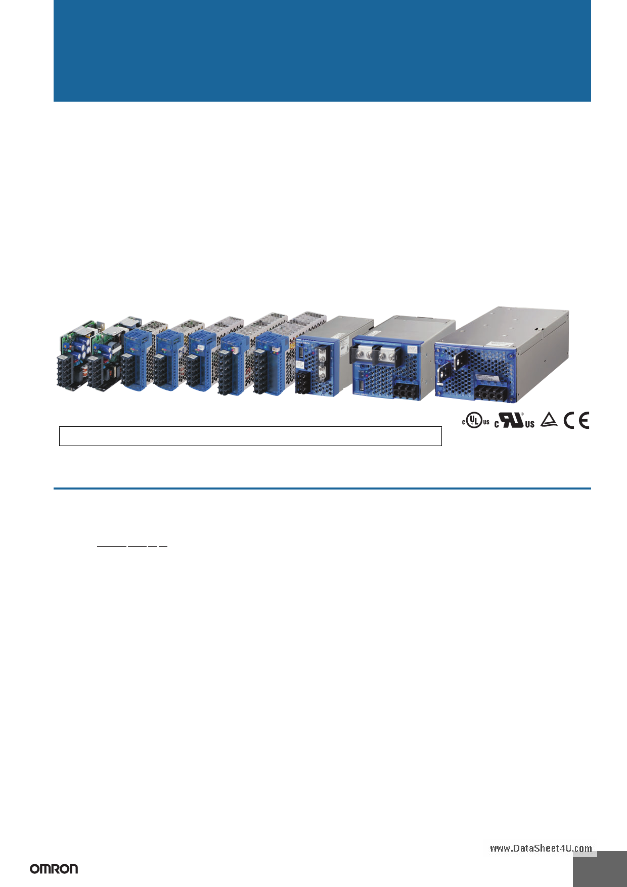
Switch Mode Power Supply
S8VM www.DataSheet4U.com
(15/30/50/100/150/300/600/1,500-W Models)
CSM_S8VM_DS_E_7_1
Power Supply Featuring OMRON’s Unique, New Undervoltage Alarm Function with
Compact Body Contributing to Machine Downsizing
• New undervoltage alarm function assists in determining causes of errors (S8VM-@@@24A@/P@ only).
• Power failure alarm function provides notification of output voltage errors (300-, 600-, and 1,500-W models only).
• Broad range of possibilities with 8 capacities and 29 models to choose from.
• RoHS-compliant
• New, attentive design prevents screws from falling out of terminal block (except for output terminals of 300-, 600-, and 1,500-W
models).
• Finger protection prevents electric shock.
• DIN Rail mounting.
• Safety standards: UL508/60950-1/1604, CSA C22.2 No. 14/No. 60950-1/No. 213, EN50178, EN60950-1 (The 300-, 600-, and
1,500-W models will not conform to safety standards if the customer replaces the fan.)
• Conforms to SEMI F47-0200 (when 200-V input is used).
• Harmonic current emissions: Conforms to EN61000-3-2 (except for 15- and 30-W models).
! Refer to Safety Precautions for All Power Supplies and Safety Precautions on page 32.
Model Number Structure
■ Model Number Legend
Note: Not all combinations are possible. Refer to List of Models in Ordering Information on page 2.
S8VM- @@@@@@@
1 2 34
1. Power Ratings
015: 15 W
030: 30 W
050: 50 W
100: 100 W
150: 150 W
300: 300 W
600: 600 W
152: 1,500 W
2. Output Voltage
05: 5 V
12: 12 V
15: 15 V
24: 24 V
3. Configuration/Functions
None: Open-frame type Standard type
C: Covered type Standard type
A: Covered type Undervoltage alarm type (Sinking)
(See note 2.)
P: Covered type Undervoltage alarm type (Sourcing)
(See note 2.)
4. Configuration
None: Bottom mounting type (See note 3.)
D: DIN Rail mounting bracket type
Note: 1. A forced-air cooling method with a fan is used with 300-, 600-, and 1,500-W models.
2. The housing and terminal of the connector for the undervoltage alarm output are provided with the S8VM-05024A@/P@, S8VM-
10024A@/P@ and S8VM-15024A@/P@.
3. Bottom mounting models cannot be used for front mounting. For a front mounting configuration, use a DIN Rail Mounting Bracket model
or Mounting Brackets (sold separately).
1
1 page 
Connections
■ Block Diagrams
S8VM-015@@@@ (15 W)
S8VM
www.DataSheet4U.com
S8VM-01524A@
Undervoltage DC LOW1
alarm indication DC LOW2
Undervoltage
detection
AC (L)
INPUT
AC (N)
Fuse
2A
Noise
filter
Rectification
Inrush Smoothing
current
protection circuit
Drive control
circuit
Rectifier/smoothing
circuit
+V
DC OUTPUT
−V
/FG
S8VM-030@@@@ (30 W)
Overcurrent
detection circuit
Photocoupler
Voltage
detection circuit
Overvoltage
detection circuit
S8VM-03024A@
Undervoltage DC LOW1
alarm indication DC LOW2
Undervoltage
detection
AC (L)
INPUT
Fuse
3.15 A
AC (N)
Noise
filter
Rectification
Inrush Smoothing
current
protection circuit
Drive control
circuit
Rectifier/smoothing
circuit
+V
DC OUTPUT
−V
Overcurrent
detection circuit
Voltage
detection circuit
Overvoltage
detection circuit
/FG Photocoupler
S8VM-050@@@@ (50 W)
AC (L)
INPUT
AC (N)
Fuse
2A
Noise
filter
Rectification Harmonic
current
suppression
Inrush Smooth-
current
protection
ing
circuit
S8VM-05024A@ (Sinking)
S8VM-05024P@ (Sourcing)
Undervoltage DC LOW1
alarm indication DC LOW2
Undervoltage
detection
Photocoupler
Alarm
DC LOW1
Alarm
DC LOW2
Common
+V
DC OUTPUT
Rectifier/smoothing
circuit
−V
Undervoltage DC LOW1
alarm indication DC LOW2
Undervoltage
detection
Photocoupler
Drive control
circuit
Alarm
DC LOW1
Alarm
DC LOW2
Common
Overcurrent
detection circuit
Voltage
detection circuit
Overvoltage
detection circuit
Photocoupler
/FG
5
5 Page 
■ Overload Protection
The Power Supply is provided with an overload protection function
that protects the Power Supply from possible damage by short-circuit
and overcurrent.
When the output current rises above 105% min. of the rated current,
the protection function is triggered, automatically decreasing the out-
put voltage. When the output current falls within the rated range, the
overload protection function is automatically cleared.
15W/30W
50W/100W/150W (5 V)
S8VM
www.DataSheet4U.com
■ Overvoltage Protection
Consider the possibility of an overvoltage and design the system so
that the load will not be subjected to an excessive voltage even if the
feedback circuit in the Power Supply fails. When an excessive
voltage that is approximately 140% of the rated voltage or more is
output, the output voltage is shut OFF, preventing damage to the load
due to overvoltage. Reset the input power by turning it OFF for at
least three minutes and then turning it back ON again.
Approx. 40%
Overvoltage protection
operating
+20%
Variable range
Intermittent operation
Intermittent operation
Rated output
voltage
*1 *2
0 50 100
Output current (%)
50W/100W/150W (12 V, 15 V, 24 V)
0 50 100
Output current (%)
300W/600W/1,500W
−10%
−20%
Note: Refer to page 17.
0V
The values shown in the above diagram are for reference only.
*1 S8VM-@@@24A@/P@
*2 Except for S8VM-@@@24A@/P@
0 50 100
Output current (%)
The values shown in the above diagrams are for reference only.
Note: 1. Internal parts may occasionally deteriorate or be damaged
if a short-circuited or other overcurrent state continues dur-
ing operation.
Do not continue an overload state for longer than 30 sec-
onds. Eliminate the overcurrent state as soon as possible.
2. Internal parts may possibly be deteriorated or damaged if the
Power Supply is used for applications with frequent inrush cur-
rent or overloading at the load end. Do not use the Power Supply
for such applications.
Note: 1. Do not turn ON the input power again until the cause of the
overvoltage has been removed.
2. The overvoltage protection function may be activated when
the output voltage adjuster (V.ADJ) is set to a value that
exceeds +20% of the rated output voltage.
3. When the +S and −S terminals are opened with the short-
bar removed, the overvoltage protection function is
activated and the output voltage will be cut off.
■ Undervoltage Alarm Function (Indication and Output)
(Only S8VM-@@@24A@/P@)
If an output voltage drop is detected with an S8VM-@@@24A@/P@ with undervoltage alarm function, the DC LOW indicator will light to notify of an
output error. The transistor also sends an output externally to notify of the error (except for the S8VM-01524A@ and S8VM-03024A@).
Transistor Output: Sinking type:
(NPN) (S8VM-@@@24A@)
Sourcing type: (PNP) (S8VM-@@@24P@)
30 VDC max., 50 mA max., Residual voltage when ON: 2 V or less, Leakage current when OFF: 0.1 mA or less
S8VM-01524A@
S8VM-03024A@
S8VM-05024A@/P@
S8VM-10024A@/P@
S8VM-15024A@/P@
8 9 10
67
8 9 10
10
4 94
4 74 7
8
66
7
6
• Undervoltage Alarm Function 1 (DC LOW1)
Only a momentary voltage drop is detected. Detection voltage is automatically adjusted internally by detecting the output voltage (approx. 2.7 V
lower than the voltage output at an output voltage of 24.0 V).
During detection, the transistor is OFF (with no continuity across 8 and 10) and the LED (6: Yellow) lights. (The Undervoltage Alarm Function 1 is
used as a latch holding function.)
• Undervoltage Alarm Function 2 (DC LOW2)
Detection voltage is set to approx. 20.0 V (from 18.0 to 21.6 V).
During detection, the transistor is OFF (with no continuity across 9 and 10) and the LED (7: Red) lights.
Note: 1. This function monitors the voltage at the Power Supply output terminals.
To check actual voltage, measure voltage on the load side.
2. Gradual voltage drop is not detected by the Undervoltage Alarm Function 1 (DC LOW1).
3. Once a voltage drop in the output voltage is detected by Undervoltage Alarm Function 1 (DC LOW1), the transistor turns OFF and status
of the LED (6: Yellow) light is maintained. To reset the function, turn OFF the input power for 60 seconds or longer, and then turn it ON
again.
4. If the output voltage remains at 15 V or lower for several seconds when using Undervoltage Alarm Function 1 (DC LOW 1), the output
hold status for detection may be reset.
11
11 Page | ||
| Páginas | Total 30 Páginas | |
| PDF Descargar | [ Datasheet S8VM.PDF ] | |
Hoja de datos destacado
| Número de pieza | Descripción | Fabricantes |
| S8VK | POWER SUPPLIES | Omron |
| S8VK-G | Switch Mode Power Supply | Omron |
| S8VK-G01505 | Switch Mode Power Supply | Omron |
| S8VK-G01512 | Switch Mode Power Supply | Omron |
| Número de pieza | Descripción | Fabricantes |
| SLA6805M | High Voltage 3 phase Motor Driver IC. |
Sanken |
| SDC1742 | 12- and 14-Bit Hybrid Synchro / Resolver-to-Digital Converters. |
Analog Devices |
|
DataSheet.es es una pagina web que funciona como un repositorio de manuales o hoja de datos de muchos de los productos más populares, |
| DataSheet.es | 2020 | Privacy Policy | Contacto | Buscar |