|
|
|
PDF 78Q2133 Data sheet ( Hoja de datos )
| Número de pieza | 78Q2133 | |
| Descripción | MicroPHY 10/100BASE-TX Transceiver | |
| Fabricantes | Teridian Semiconductor | |
| Logotipo | ||
Hay una vista previa y un enlace de descarga de 78Q2133 (archivo pdf) en la parte inferior de esta página. Total 38 Páginas | ||
|
No Preview Available !
Simplifying System IntegrationTM
DESCRIPTION
The 78Q2123 and 78Q2133, MicroPHYTM, are the
smallest 10BASE-T/100BASE-TX Fast Ethernet
transceivers in the market. They include integrated
MII, ENDECs, scrambler/descrambler, dual-speed
clock recovery, and full-featured auto-negotiation
functions. The transmitter includes an on-chip pulse-
shaper and a low-power line driver. The receiver has
an adaptive equalizer and a baseline restoration
circuit required for accurate clock and data recovery.
The transceiver interfaces to Category-5 unshielded
twisted pair (Cat-5 UTP) cabling for 100BASE-TX
applications, and Category-3 unshielded twisted pair
(Cat-3 UTP) for 10BASE-T applications. The MDI is
connected to the line media via dual 1:1 isolation
transformers. No external filter is required. Interface
to the MAC is accomplished through an IEEE-802.3
compliant Media Independent Interface (MII). The
78Q2123/78Q2133 are intended to serve the
embedded Ethernet market, tailored specifically to the
needs of game consoles, broadband modems,
printers, set top boxes and audio/visual equipment. It
is designed for low-power consumption and operates
from a single 3.3V supply. The 78Q2123 is rated for
commercial temperature range and the 78Q2133 is
rated for industrial temperature range.
78Q2123/78Q2133 MicroPHY™www.DataSheet4U.com
10/100BASE-TX Transceiver
DATA SHEET
April 2010
FEATURES
• Smallest 10/100 PHY available
• 10BASE-T/100BASE-TX IEEE-802.3 compliant
TX and RX functions requiring a dual 1:1 isolation
transformer interface to the line
• Integrated MII, 10BASE-T/100BASE-TX ENDEC,
100BASE-TX scrambler/descrambler, and
full-featured auto-negotiation function
• Full duplex operation capable
• Automatic MDI/MDI-X cross over correction
• Register-programmable transmit amplitude
• Automatic polarity correction during auto-
negotiation and 10BASE-T signal reception
• Power-saving and power-down modes including
transmitter disable
• 2 Programmable LED indicators (Link and
Activity by default)
• User programmable Interrupt pin
• Package: 32-QFN (5x5 mm)
• Low Power (~290mW)
• Single 3.3 V ± 0.3V Supply
• 78Q2123 rated for 0°C to 70°C operation
• 78Q2133 rated for -40°C to 85°C operation
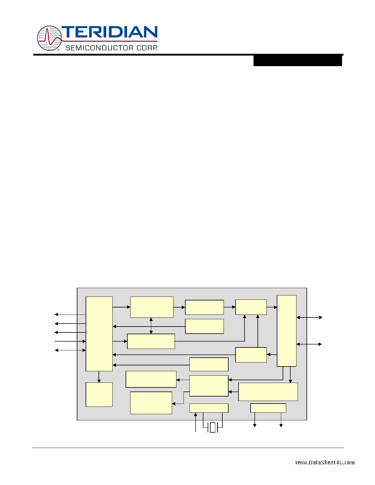
RXC
TXC
RXD
TXD
SMI
Rev. 1.6
100M
4B/5B Encoder,
Scrambler,
Parallel/Serial
MII
10M Parallel/Serial,
Manchester Encoder
MII
Registers
Manchester Decoder,
Parallel/Serial
Serial/Parallel
Descrambler,
5B/4B Decoder
MRZ/NRZI
MLT3 Encoder
TX CLK GEN
Carrier Sense,
Collision Detect
CLK
Recovery
Clock Reference
Pulse Shaper
and Filter
Auto
Negotiation
Auto
MDI-X
Mux
Tx/Rx
Rx/Tx
10M 100M
Adaptive EQ,
Baseline Wander Correct,
MLT3 Decode, NRZI/NRZ
LEDs
CLKIN 25MHz
Link
© 2010 Teridian Semiconductor Corporation
Act
1
1 page 
DS_21x3_001
78Q2123/78Q213w3wDwa.DtaataSShheeete4Ut .com
1 Functional Description
1.1 General
1.1.1 Power Management
The 78Q2123 and 78Q2133 have three power saving modes:
• Chip Power-Down
• Receive Power Management
• Transmit High Impedance Mode
Chip power-down is activated by setting the PWRDN bit in MII register MR0.11. When the chip is in
power-down mode, all on-chip circuitry is shut off, and the device consumes minimum power. While in
the power-down state, the 78Q2123/78Q2133 still respond to management transactions.
Receive power management (RXCC mode) is activated by setting the RXCC bit in MII register MR16.0.
In this mode of operation, the adaptive equalizer, the clock recovery phase lock loop (PLL), and all other
receive circuitry will be powered down when no valid MLT-3 signal is present at the UTP receive line
interface. As soon as a valid signal is detected, all circuits will automatically be powered up to resume
normal operation. During this mode of operation, RX_CLK will be inactive when there is no data being
received. Note that the RXCC mode is not supported during 10BASE-T operation.
Transmit high impedance mode is activated by setting the TXHIM bit in MII register MR16.12. In this
mode of operation, the transmit UTP drivers are in a high impedance state and TX_CLK is tri-stated. A
weak internal pull-up is enabled on TX_CLK. The receive circuitry remains fully operational. The default
state of MR16.12 is a logic low for disabling the transmit high impedance mode. Only a reset condition will
automatically clear MR16.12. The transmitter is fully functional when MR16.12 is cleared. This feature is
useful when configuring a system for Wake-On LAN (when the 78Q2123/78Q2133 are coupled with a
Wake-On LAN capable MAC).
1.1.2 Analog Biasing and Supply Regulation
The 78Q2123/78Q2133 require no external component to generate on-chip bias voltages and currents.
High accuracy is maintained through a closed-loop trimmed biasing network.
On-chip digital logic runs off an internal voltage regulator. Hence only a single 3.3V (± 0.3V) supply is
required to power-up the device. The on-chip regulator is not affected by the power-down mode.
1.1.3 Clock Selection
The 78Q2123/78Q2133 have an on-chip crystal oscillator which can also be driven by an external oscillator.
In this mode of operation, a 25 MHz crystal should be connected between the XTLP and XTLN pins.
Alternatively, an external 25 MHz clock input can be connected to the XTLP pin. In this mode of operation,
a crystal is not required and the XTLN pin must be tied to ground.
1.1.4 Transmit Clock Generation
The transmitter uses an on-chip frequency synthesizer to generate the transmit clock. In 100BASE-TX
operation, the synthesizer multiplies the reference clock by 5 to obtain the internal 125 MHz serial transmit
clock. In 10BASE-T mode, it generates an internal 20MHz transmit clock by multiplying the reference
25 MHz clock by 4/5. The synthesizer references either the local 25 MHz crystal oscillator, or the externally
applied clock, depending on the selected mode of operation.
Rev. 1.6
5
5 Page 
DS_21x3_001
78Q2123/78Q213w3wDwa.DtaataSShheeete4Ut .com
2 Pin Description
2.1 Legend
Type
A
CIU
CIS
CO
S
Description
Analog Pin
TTL-level Input with Pull-up
TTL-level Input with Schmitt Trigger
CMOS Output
Supply
Type
CI
CIO
COZ
Description
TTL-level Input
TTL-compatible Bi-directional Pin
Tristate-able CMOS Output
G Ground
2.2 MII (Media Independent Interface)
Signal
TX_CLK
TX_EN
TXD[3:0]
TX_ER
CRS
COL
RX_CLK
RX_DV
Pin
15
Type
COZ
16 CI
[20:17] CI
14 CI
22 COZ
21 COZ
12 COZ
11 COZ
Description
TRANSMIT CLOCK: TX_CLK is a continuous clock, which provides a
timing reference for the TX_EN, TX_ER and TXD[3:0] signals from the
MAC. The clock frequency is 25 MHz in 100BASE-TX mode and 2.5 MHz
in 10BASE-T mode. This pin is tri-stated in isolate mode and the TXHIM
mode.
TRANSMIT ENABLE: TX_EN is asserted by the MAC to indicate that
valid data for transmission is present on the TXD[3:0] pins.
TRANSMIT DATA: TXD[3:0] receives data from the MAC for transmission
on a nibble basis. This data is captured on the rising edge of TX_CLK
when TX_EN is high.
TRANSMIT ERROR: TX_ER is asserted high by the MAC to request that
an error code-group be transmitted when TX_EN is high. In PCS bypass
mode, this pin becomes the MSB of the transmit 5-bit code group.
CARRIER SENSE: When the 78Q2123/78Q2133 are not in repeater
mode, CRS is high whenever a non-idle condition exists on either the
transmitter or the receiver. In repeater mode, CRS is only active when a
non-idle condition exists on the receiver. This pin is tri-stated in isolate
mode.
COLLISION: COL is asserted high when a collision has been detected on
the media. In 10BASE-T mode COL is also used for the SQE test function.
This pin is tri-stated in isolate mode. During half duplex operation, the
rising edge of COL will occasionally occur upon the rising edge of
TX_CLK.
RECEIVE CLOCK: RX_CLK is a continuous clock, which provides a
timing reference to the MAC for the RX_DV, RX_ER and RXD[3:0] signals.
The clock frequency is 25 MHz in 100BASE-TX mode and 2.5 MHz in
10BASE-T mode. To reduce power consumption in 100BASE-TX mode,
the 78Q2123/78Q2133 provide an optional mode, enabled through
MR16.0, in which RX_CLK is held inactive (low) when no receive data is
detected. This pin is tri-stated in isolate mode.
RECEIVE DATA VALID: RX_DV is asserted high to indicate that valid
data is present on the RXD[3:0] pins. In 100BASE-TX mode, it transitions
high with the first nibble of the preamble and is pulled low when the last
data nibble has been received. In 10BASE-T mode it transitions high when
the start-of-frame delimiter (SFD) is detected. This pin is tri-stated in
isolate mode.
Rev. 1.6
11
11 Page | ||
| Páginas | Total 38 Páginas | |
| PDF Descargar | [ Datasheet 78Q2133.PDF ] | |
Hoja de datos destacado
| Número de pieza | Descripción | Fabricantes |
| 78Q2133 | MicroPHY 10/100BASE-TX Transceiver | Teridian Semiconductor |
| Número de pieza | Descripción | Fabricantes |
| SLA6805M | High Voltage 3 phase Motor Driver IC. |
Sanken |
| SDC1742 | 12- and 14-Bit Hybrid Synchro / Resolver-to-Digital Converters. |
Analog Devices |
|
DataSheet.es es una pagina web que funciona como un repositorio de manuales o hoja de datos de muchos de los productos más populares, |
| DataSheet.es | 2020 | Privacy Policy | Contacto | Buscar |