|
|
|
PDF ETPW Data sheet ( Hoja de datos )
| Número de pieza | ETPW | |
| Descripción | Radial-Leaded Solid Tantalum Capacitors | |
| Fabricantes | Vishay Siliconix | |
| Logotipo | ||
Hay una vista previa y un enlace de descarga de ETPW (archivo pdf) en la parte inferior de esta página. Total 7 Páginas | ||
|
No Preview Available !
ETPW
Vishay Roederstein
www.DataSheet4U.com
Resin-Coated, Radial-Leaded
Solid Tantalum Capacitors
FEATURES
• Flame retardant encapsulation
• Practically without epoxy run down
• Very high temperature range
• Improved humidity class
• Low leakage current
• Very high CV product
• Low temperature dependence
• Low failure rate
• High operational reliability
MECHANICAL SPECIFICATIONS
Colour: Gold
Laser Marked: Capacity and voltage in clear text;
Plus pole marked
Leads : Tinned
Tantalum capacitors with sintered anode and solid
semiconductor electrolyte with flame retardant fluidized bed
coating. The type ETPW is characterized by very favorable
electrical values even at higher ambient temperatures. The
capacitors comply with DIN 45910 part 146 and they are also
available as a radially taped version.
ORDERING INFORMATION
P1A 685
TYPE
CAPACITANCE
603
DC VOLTAGE RATING
@ + 85°C
ETPW 1A ....
ETPW 6R
Expressed in picofarads.
The first two digits are
significant figures. The
third is the number of
zeros following.
Expressed by zeros if
needed to complete the 3
digit block. A decimal point
is indicated by an “0“ (603
= 6.3 Volts)
M
CAPACITANCE
TOLERANCE
M = ± 20%
K = ± 10%
00
LEAD STYLES AND
PACKAGING
See Lead styles
and
packaging table
D
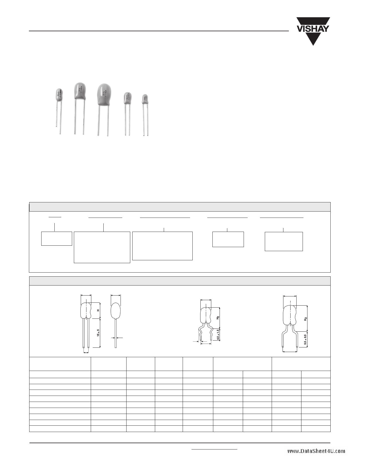
DIMENSIONS in millimeters
BASIC VERSION
DD
FORM DS
D
FORM L
D
ød
1.1 ± 0.1
RM ± 0.5
MODEL
ETPW - 1 A,B
ETPW - 2 C,D
ETPW - 2 E
ETPW - 3 F
ETPW - 3 G
ETPW - 4 H
ETPW - 5 J,K*
ETPW - 5 J,K,L
ETPW - 6 M,N
ETPW - 6 P,R
RM ± 0.5
D MAX.
4.0
4.5
5.0
5.0
5.5
6.0
8.6
8.6
9.5
9.5
H MAX.
7.1
8.0
9.5
9.5
10.0
10.0
12.5
12.5
15.0
16.0
RM
± 0.5
2.5
2.5
2.5
2.5
2.5
2.5
2.5
5.0
5.0
5.0
ØD±0.05
0.5
0.5
0.5
0.5
0.5
0.5
0.5
0.5
0.5
0.5
FORM DS
H2 MAX
RM
10.5 5
11.0 5
12.5 5
12.5 5
13.0 5
13.0 5
15.5 5
15.5 5
18.0 5
19.0 5
*J,K with RM 2.5mm : 100µF-6.3V, 68µF-10V, 47µF-16V, 22µF - 25V
www.vishay.com
120
For technical questions, contact [email protected]
RM ± 0.5
FORM L
H2 MAX
RM
10.5 5
11.0 5
12.5 5
12.5 5
13.0 5
13.0 5
15.5 5
--
--
--
Document Number 42074
Revision 15-Aug-02
1 page 
ETPW
Vishay Roederstein
Resin-Coated, Radial-Leaded
Solid Tantalum Capacitors
www.DataSheet4U.com
PERFORMANCE CHARACTERISTICS
1. Climatic Category : 55/125/56 acc. to IEC
2. Temperature Range: - 55°C up to + 125°C with linear
voltage derating to category voltage UC
11. Permissible AC Voltage Stress: The highest
permissible AC voltage for the respective frequency may
be taken from the brochure “General information”.
The values apply for + 20°C For higher temperatures,
the values have to be multiplied with the following factors:
3. Rated Voltage, Category Voltage: 3V_ to 50V_;
2V_ to 33V_
TEMPERATURE
+ 50°C
+ 85°C
+ 125°C.
FACTOR
0.7
0.5
0.3
4. Surge Voltage: 1.3 times of rated voltage at + 85°C
5. Reverse Voltage (Temporary):
15% of the rated DC voltage at + 20°C
10% of the rated DC voltage at + 55°C
5% of the rated DC voltage at + 85°C
Intermediate values can be obtained by linear
interpolation.
For further notes on AC voltage stress: See general
information
12. Service life : > 300.000 h**
6. Rated Capacitance: 0.1µF to 330µF
13. Failure percentage: ≤ 0.6% within 100.000 h**
7. Capacitance Tolerance : ± 20%, ± 10%,
14. Failure rate (λ): ≤ 0.6 10-7 /h = ≤ 60 fit**
8. Leakage Current in µA: Measured at + 20°C after 5
minutes: ≤ 0.01 x CR x UR or 0.5 µA, whichever
is greater
9. Dissipation Factor: at 120Hz and + 20°C
See table
15. Failure criteria: Catastrophic failure : Short circuit or
interruption
Drift failure: ∆C/C > +5 - 15%
Z > 3 times initial limit value
IR > 5 times initial value + 5µA
** related to UR, + 40°C and a circuit resistance of ≥ 3 Ω/V
10. Impedance: Measured at 100kHz and + 20°C
See table.
16. Characteristics at high and low temperatures (the values shall not exceed the following limits)
TEST TEMPERATURE
∆C/C <
tanδ
≤ 1.5µF
< 10µF
< 100µF
≥ 100µF
Leakage current IR
- 55°C
- 10%
0.04
0.06
0.08
0.10
-
+ 20°C
-
0.04
0.06
0.08
0.10
≤ 0.01 x CR x UR
or 0.5µA
whichever is greater
+ 85°C
+ 12%
0.04
0.06
0.08
0.10
≤ 0.1 x CR x UR
or 10µA
whichever is greater
+ 125°C
+ 15%
0.06
0.08
0.08
0.10
≤ 0.125 x CR x UR
or 12.5µA
whichever is greater*
*Measured at category voltage
www.vishay.com
124
For technical questions, contact [email protected]
Document Number 42074
Revision 15-Aug-02
5 Page | ||
| Páginas | Total 7 Páginas | |
| PDF Descargar | [ Datasheet ETPW.PDF ] | |
Hoja de datos destacado
| Número de pieza | Descripción | Fabricantes |
| ETP01-1621 | Protection | STMicroelectronics |
| ETP01-2821 | Protection | STMicroelectronics |
| ETP01-xx21 | Protection | STMicroelectronics |
| ETPW | Radial-Leaded Solid Tantalum Capacitors | Vishay Siliconix |
| Número de pieza | Descripción | Fabricantes |
| SLA6805M | High Voltage 3 phase Motor Driver IC. |
Sanken |
| SDC1742 | 12- and 14-Bit Hybrid Synchro / Resolver-to-Digital Converters. |
Analog Devices |
|
DataSheet.es es una pagina web que funciona como un repositorio de manuales o hoja de datos de muchos de los productos más populares, |
| DataSheet.es | 2020 | Privacy Policy | Contacto | Buscar |