|
|
|
PDF AAT2687 Data sheet ( Hoja de datos )
| Número de pieza | AAT2687 | |
| Descripción | PMIC Solution | |
| Fabricantes | Advanced Analogic Technologies | |
| Logotipo | ||
Hay una vista previa y un enlace de descarga de AAT2687 (archivo pdf) en la parte inferior de esta página. Total 20 Páginas | ||
|
No Preview Available !
SystemPowerTM
PRODUCT DATASHEET
AAT2687
PMIC Solution for 24V Systems with 2 High Performance Step-Down Converters
General Description
The AAT2687 provides two independently regulated DC
outputs; consisting of a high voltage step-down regula-
tor and a low input voltage low dropout (LDO) regulator.
The PMIC is optimized for low-cost 12V adapter inputs,
making the device the ideal system-on-a-chip power
solution for consumer communications equipment.
Channel 1 is a step-down regulator with an input voltage
range 6.0 to 24V, providing up to 4.5A output current.
490kHz fixed switching frequency allows small L/C filter-
ing components. Channel 1 utilizes voltage mode control
configured for optimum performance across the entire
output voltage and load range.
Channel 2 is a low-dropout (LDO) regulator providing up
to 600mA output current. The device provides extremely
low output noise, low quiescent current and excellent
transient response.
The controller includes integrated cycle-by-cycle over-
current protection, soft-start and over-temperature dis-
able features. Independent input and enable pins pro-
vide maximum design flexibility.
The AAT2687 is available in the Pb-free, 4x5mm 24-pin
TQFN package. The rated operating temperature range is
-40°C to 85°C.
Features
• 2-Output Step-Down Converters:
▪ Channel 1 Step-Down: VIN1 = 6V to 24V
• VOUT1 Adjustable from 1.5V to 5.5V
• IOUT1 up to 4.5A
• High Switching Frequency
• Voltage Mode Control
• PWM Fixed Frequency for Low-Ripple
▪ Channel 2 (LDO): VIN2 = 2.7V to 5.5V
• IOUT2 up to 600mA
• 1V Dropout Voltage at 600mA
• High Accuracy ±1.5%
• Small Solution Size
▪ System On a Chip
▪ Ultra-small External L/C
• Shutdown Current <35μA
• Independent Enable Pins
• Programmable Over-Current Protection
• Over-Temperature Protection
• Internal Soft Start
• 4x5mm 24-Pin TQFN Low Profile Thermally Enhanced
Package
• -40°C to 85°C Temperature Range
Applications
• DSL and Cable Modems
• Notebook Computers
• Satellite Settop Box
• Wireless LAN Systems
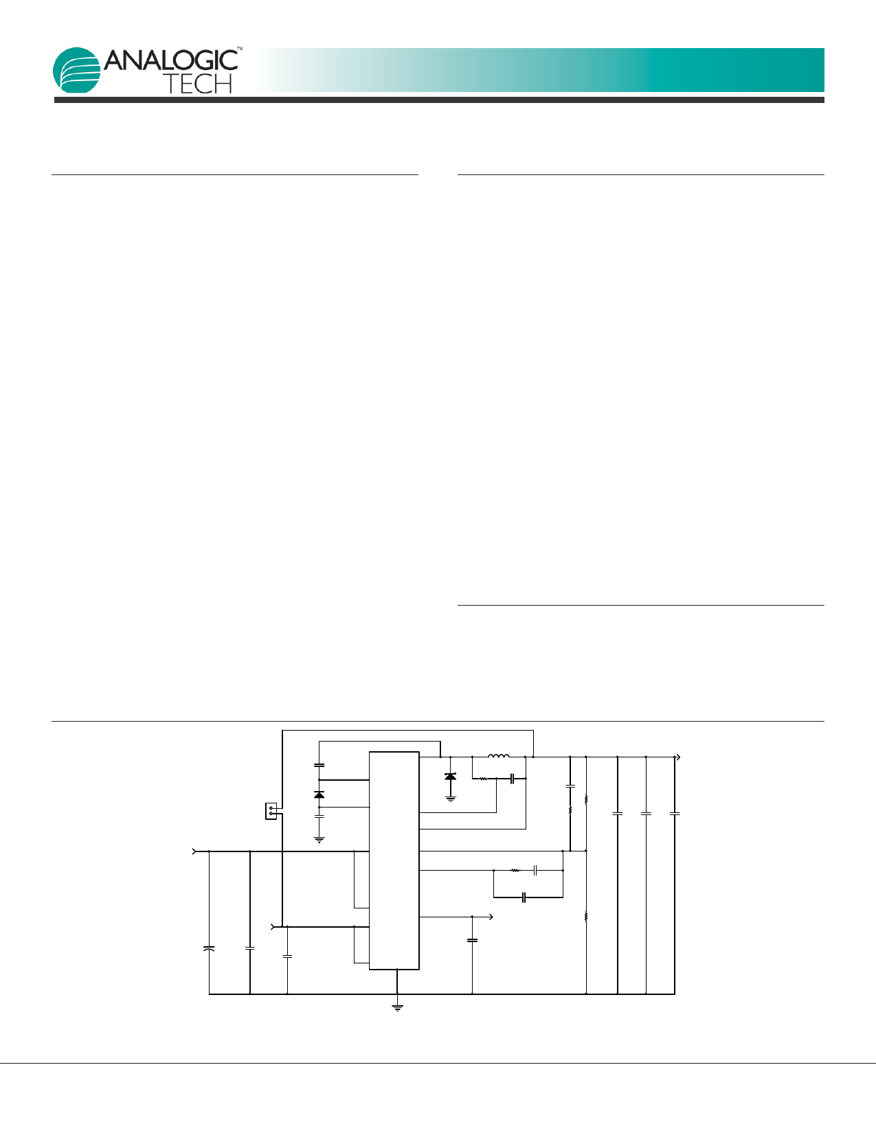
Typical Application
VIN1
6.0V - 24.0V
J1
2
1
C3
0.1µF
D1
BAS16
C14
2.2µF
+ C1
220µF
25V
VIN2
C13
1µF
25V
C2
2.2µF
LX1
BST
VL1 RS1
OS1
IN1 FB1
L1
4.7µH 5.3A
D2
R2 C4
2k 220nF
C10
2.2nF
R5
450
VOUT1
3.3V/4.5A
R3
8.87k
C7 C8 C9
22µF 22µF 22µF
COMP1
AAT2687
EN1
OUT2
IN2
EN2 GND
TQFN45-24
R1 C5
3.92K 2.2nF
C6
VOUT2 150pF
1.8V/600mA
R4
1.96k
C12
2.2µF
2687.2008.06.1.0
www.DataSheet.in
www.analogictech.com
1
1 page 
SystemPowerTM
PRODUCT DATASHEET
AAT2687
PMIC Solution for 24V Systems with 2 High Performance Step-Down Converters
Typical Characteristics—Channel 1
Step-Down Converter Efficiency vs. Load Current
100
90
80
70
60
50
40
30
20
10
0
0.001
0.01
0.1
VIN1 = 6V
VIN1 = 7V
VIN1 = 8V
VIN1 = 12V
VIN1 = 18V
VIN1 = 24V
1 10
Load Current (A)
Step-Down Converter Load Regulation
vs. Load Current
2
1.5
1
0.5
0
-0.5
-1
-1.5
-2
0.001
VIN1 = 6V
VIN1 = 7V
VIN1 = 8V
VIN1 = 12V
VIN1 = 18V
VIN1 = 24V
0.01
0.1
1
10
Load Current (A)
Step-Down Converter Line Regulation
vs. Load Current
2
IOUT1 = 0.1µA
1.5 IOUT1 = 2.25A
1 IOUT1 = 3.5A
IOUT1 = 4mA
0.5 IOUT1 = 4.5A
0
-0.5
-1
-1.5
-2
6
9 12 15 18 21 24
Input Voltage (V)
No Load Step-Down Converter Input Current
vs. Input Voltage
650
625
600
575
550
525
500
475
450
6
85°C
25°C
-40°C
9 12 15 18 21 24
Input Voltage (V)
Step-Down Converter Switching Frequency
vs. Input Voltage
(VOUT1 = 3.3V; IOUT1 = 4.5A)
8
85°C
6 25°C
4 -40°C
2
0
-2
-4
-6
-8
6
8 10 12 14 16 18 20 22 24
Input Voltage (V)
Step-Down Converter Output Voltage
vs. Temperature
(VOUT = 3.3V; IOUT1 = 4.5A; COUT1 = 66µF; L = 4.7µH; VIN1 = 12V)
1
0.75
0.5
0.25
0
-0.25
-0.5
-0.75
-1
-40 -15 10 35 60 85
Temperature (°C)
2687.2008.06.1.0
www.DataSheet.in
www.analogictech.com
5
5 Page 
SystemPowerTM
PRODUCT DATASHEET
AAT2687
PMIC Solution for 24V Systems with 2 High Performance Step-Down Converters
Channel 1 Feedback and
Compensation Networks
C6
C5 R1
C10
R5 VOUT1
COMP1
R3
FB1
R4
REF
Figure 1: AAT2687 Feedback and Compensation
Networks for Type III Voltage-Mode Control Loop.
The transfer function of the Error Amplifier is dominated
by the DC Gain and the L COUT output filter of the regula-
tor. This output filter and its equivalent series resistor
(ESR) create a double pole at FLC and a zero at FESR in the
following equations:
Eq.
1:
FLC
=
2
·
π
·
1
L
·
COUT
Eq.
2:
FESR
=
2
·
π
·
1
ESR
·
COUT
The feedback and compensation networks provide a
closed loop transfer function with the highest 0dB cross-
ing frequency and adequate phase margin for system
stability. Equation 3, 4, 5 and 6 relate the compensation
network’s poles and zeros to the components R1, R3,
R5, C5, C6, and C10:
Eq.
3:
FZ1
=
2
·
π
1
· R1
·
C5
Eq.
4:
FZ1
=
2
·
π
·
1
(R3 +
R5)
·
C10
Eq. 5: FP1 =
1
2 · π · R1 ·
C5 · C6
C5 + C6
Eq. 6: FP2 =
1
2 · π · R5 · C10
Components of the feedback, feed forward, compensa-
tion, and current limit networks need to be adjusted to
maintain the systems stability for different input and
output voltages applications as shown in Table 1.
Channel 1 Thermal Protection
The AAT2687 has an internal thermal protection circuit
which will turn on when the device die temperature
exceeds 135°C. The internal thermal protection circuit
will actively turn off the high side regulator output
device to prevent the possibility of over temperature
damage. The Buck regulator output will remain in a
shutdown state until the internal die temperature falls
back below the 135°C trip point. The combination and
interaction between the short circuit and thermal protec-
tion systems allows the Buck regulator to withstand
indefinite short-circuit conditions without sustaining per-
manent damage.
Network
Feedback
Feed-forward
Compensation
Current Limit
Components
R4
R3
C10
R5
C5
C6
R1
C4
R2
R6
R7
R8
VOUT =3.3V
VIN = 6V-24V
1.96kΩ
8.87kΩ
2.2nF
453Ω
2.2nF
150pF
3.92kΩ
220nF
2kΩ
Open
2kΩ
165kΩ
VOUT = 5.0V
VIN = 6V-24V
1.96kΩ
8.87kΩ
2.2nF
453Ω
2.2nF
150pF
3.92kΩ
220nF
2kΩ
Open
2kΩ
165kΩ
Table 1: AAT2687 Feedback, Compensation, and Current Limit Components For VOUT = 3.3V and VOUT = 5.0V.
2687.2008.06.1.0
www.analogictech.com
11
www.DataSheet.in
11 Page | ||
| Páginas | Total 20 Páginas | |
| PDF Descargar | [ Datasheet AAT2687.PDF ] | |
Hoja de datos destacado
| Número de pieza | Descripción | Fabricantes |
| AAT2687 | PMIC Solution | Advanced Analogic Technologies |
| AAT2687 | PMIC Solution | Skyworks |
| AAT2688 | 4.5A PMIC Solution | Advanced Analogic Technologies |
| AAT2688 | 4.5A PMIC Solution | Skyworks |
| Número de pieza | Descripción | Fabricantes |
| SLA6805M | High Voltage 3 phase Motor Driver IC. |
Sanken |
| SDC1742 | 12- and 14-Bit Hybrid Synchro / Resolver-to-Digital Converters. |
Analog Devices |
|
DataSheet.es es una pagina web que funciona como un repositorio de manuales o hoja de datos de muchos de los productos más populares, |
| DataSheet.es | 2020 | Privacy Policy | Contacto | Buscar |