|
|
|
PDF STU90N4F3 Data sheet ( Hoja de datos )
| Número de pieza | STU90N4F3 | |
| Descripción | Power MOSFET ( Transistor ) | |
| Fabricantes | STMicroelectronics | |
| Logotipo | ||
Hay una vista previa y un enlace de descarga de STU90N4F3 (archivo pdf) en la parte inferior de esta página. Total 16 Páginas | ||
|
No Preview Available !
STD90N4F3 - STI90N4F3
STP90N4F3 - STU90N4F3
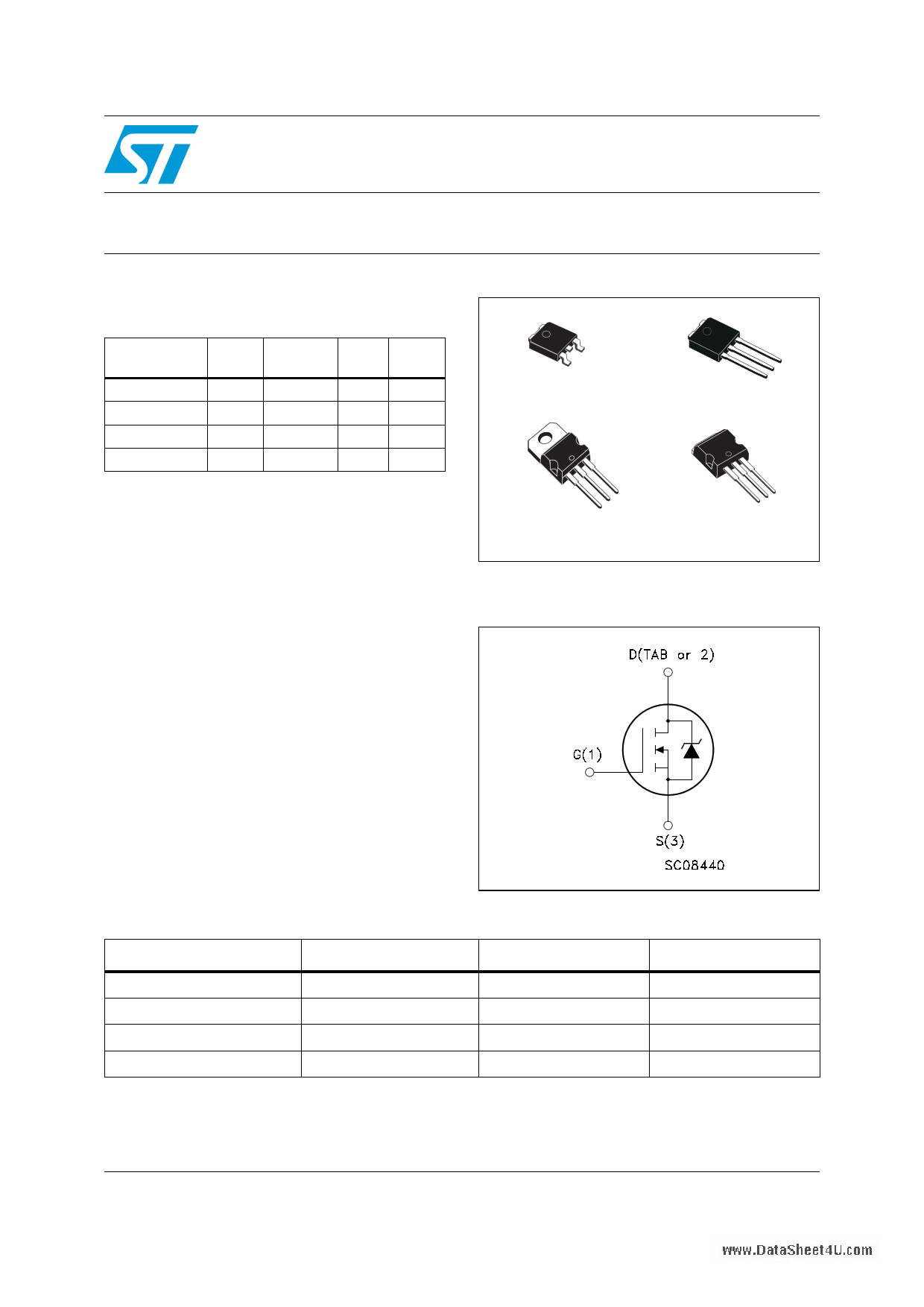
N-channel 40 V, 5.4 mΩ, 80 A, DPAK, TO-220, IPAK, I2PAK
STripFET™ Power MOSFET
Features
Type
STD90N4F3
STI90N4F3
STP90N4F3
STU90N4F3
VDSS
40 V
40 V
40 V
40 V
RDS(on)
max
< 6.5 mΩ
< 6.5 mΩ
< 6.5 mΩ
< 6.5 mΩ
ID
80 A
80 A
80 A
80 A
Pw
110 W
110 W
110 W
110 W
■ Standard threshold drive
■ 100% avalanche tested
Application
■ Switching applications
Description
This n-channel enhancement mode Power
MOSFET is the latest refinement of
STMicroelectronics unique “single feature size“
strip-based process with less critical alignment
steps and therefore a remarkable manufacturing
reproducibility. The resulting transistor shows
extremely high packing density for low on-
resistance, rugged avalanche characteristics and
low gate charge.
3
1
DPAK
IPAK
3
2
1
3
2
1
TO-220
123
I²PAK
Figure 1. Internal schematic diagram
Table 1. Device summary
Order codes
STD90N4F3
STI90N4F3
STP90N4F3
STU90N4F3
www.DataSheet4U.com
Marking
90N4F3
90N4F3
90N4F3
90N4F3
Package
DPAK
I²PAK
TO-220
IPAK
July 2008
Rev 2
Packaging
Tape & reel
Tube
Tube
Tube
1/16
www.st.com
16
1 page 
STD90N4F3 - STI90N4F3 - STP90N4F3 - STU90N4F3
Electrical characteristics
Table 6. Switching on/off (inductive load)
Symbol
Parameter
Test conditions
td(on)
tr
Turn-on delay time
Rise time
VDD=20 V, ID= 40 A,
RG=4.7 Ω, VGS=10 V
(see Figure 16)
td(off)
tf
Turn-off delay time
Fall time
VDD=20 V, ID= 40 A,
RG=4.7 Ω, VGS=10 V
(see Figure 16)
Min. Typ. Max. Unit
15 ns
50 ns
40 ns
15 ns
Table 7. Source drain diode
Symbol
Parameter
Test conditions
ISD
ISDM (1)
VSD (2)
Source-drain current
Source-drain current (pulsed)
Forward on voltage
trr
Qrr
IRRM
Reverse recovery time
Reverse recovery charge
Reverse recovery current
ISD=80 A, VGS=0
ISD=80 A,
di/dt = 100 A/µs,
VDD=30 V, Tj=150°C
(see Figure 15)
1. Pulse width limited by safe operating area
2. Pulsed: pulse duration = 300 µs, duty cycle 1.5%
Min. Typ. Max. Unit
80 A
320 A
1.5 V
45 ns
60 nC
2.8 A
www.DataSheet4U.com
5/16
5 Page 
STD90N4F3 - STI90N4F3 - STP90N4F3 - STU90N4F3
Package mechanical data
DIM.
A
A1
b
b2
b4
c
c2
D
E
e
e1
H
L
(L1)
L2
V1
TO-251 (IPAK) mechanical data
min.
2.20
0.90
0.64
mm.
typ
5.20
0.45
0.48
6.00
6.40
2.28
4.40
16.10
9.00
0.80
0.80
10 o
max.
2.40
1.10
0.90
0.95
5.40
0.60
0.60
6.20
6.60
4.60
9.40
1.20
www.DataSheet4U.com
0068771_H
11/16
11 Page | ||
| Páginas | Total 16 Páginas | |
| PDF Descargar | [ Datasheet STU90N4F3.PDF ] | |
Hoja de datos destacado
| Número de pieza | Descripción | Fabricantes |
| STU90N4F3 | N-channel Power MOSFET | STMicroelectronics |
| STU90N4F3 | Power MOSFET ( Transistor ) | STMicroelectronics |
| Número de pieza | Descripción | Fabricantes |
| SLA6805M | High Voltage 3 phase Motor Driver IC. |
Sanken |
| SDC1742 | 12- and 14-Bit Hybrid Synchro / Resolver-to-Digital Converters. |
Analog Devices |
|
DataSheet.es es una pagina web que funciona como un repositorio de manuales o hoja de datos de muchos de los productos más populares, |
| DataSheet.es | 2020 | Privacy Policy | Contacto | Buscar |