|
|
|
PDF ADP1875 Data sheet ( Hoja de datos )
| Número de pieza | ADP1875 | |
| Descripción | (ADP1874 / ADP1875) Synchronous Buck Controller | |
| Fabricantes | Analog Devices | |
| Logotipo | ||
Hay una vista previa y un enlace de descarga de ADP1875 (archivo pdf) en la parte inferior de esta página. Total 30 Páginas | ||
|
No Preview Available !
www.DataSheet4U.net
Synchronous Buck Controller with Constant
On-Time and Valley Current Mode
ADP1874/ADP1875
FEATURES
Power input voltage range: 2.95 V to 20 V
On-board bias regulator
Minimum output voltage: 0.6 V
0.6 V reference voltage with ±1.0% accuracy
Supports all N-channel MOSFET power stages
Available in 300 kHz, 600 kHz, and 1.0 MHz options
No current-sense resistor required
Power saving mode (PSM) for light loads (ADP1875 only)
Resistor programmable current limit
Power good with internal pull-up resistor
Externally programmable soft start
Thermal overload protection
Short-circuit protection
Standalone precision enable input
Integrated bootstrap diode for high-side drive
Starts into a precharged output
Available in a 16-lead QSOP package
APPLICATIONS
Telecom and networking systems
Mid- to high-end servers
Set-top boxes
DSP core power supplies
GENERAL DESCRIPTION
The ADP1874/ADP1875 are versatile current mode, synchronous
step-down controllers. They provide superior transient response,
optimal stability, and current-limit protection by using a constant
on-time, pseudo fixed frequency with a programmable current
limit, current control scheme. In addition, these devices offer
optimum performance at low duty cycles by using a valley, current
mode control architecture. This allows the ADP1874/ADP1875
to drive all N-channel power stages to regulate output voltages
to as low as 0.6 V.
The ADP1875 is the power saving mode (PSM) version of
the device and is capable of pulse skipping to maintain output
regulation while achieving improved system efficiency at light
loads (see the ADP1875 Power Saving Mode (PSM) section for
more information).
Available in three frequency options (300 kHz, 600 kHz, and
1.0 MHz, plus the PSM option), the ADP1874/ADP1875 are well
suited for a wide range of applications that require a single-input
power supply range from 2.95 V to 20 V. Low voltage biasing is
supplied via a 5 V internal low dropout regulator (LDO).
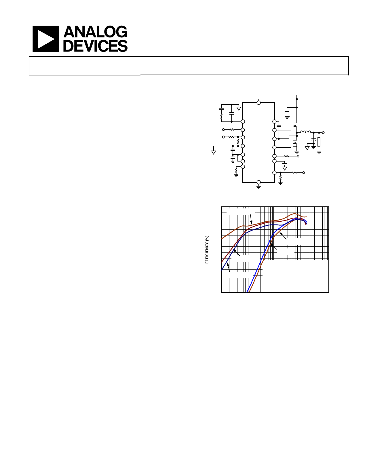
TYPICAL APPLICATIONS CIRCUIT
VIN = 2.95V TO 20V
CC
RC CC2
VREG
VOUT
10kΩ
RTOP
RBOT
CVREG2
CVREG
RRES
VIN
ADP1874/
ADP1875
COMP BST
EN DRVH
FB SW
GND
DRVL
VREG PGOOD
VREG_IN SS
RES
TRACK
PGND
CIN
CBST
Q1 L
COUT
Q2
VOUT
LOAD
RPGD
VEXT
CSS
RTRK2
RTRK1
VMASTER
Figure 1. Typical Applications Circuit
100
95 VIN = 5V (PSM)
90
85
80
75
70 VIN = 16.5V
65
60 VIN = 13V
55 VIN = 13V (PSM)
50
45
40 VIN = 16.5V (PSM)
35
30
25
10
100
TA = 25°C
fVSOWUT=
= 1.8V
300kHz
WÜRTH INDUCTOR:
744325120, L = 1.2µH, DCR = 1.8mΩ
INFINEON FETs:
BSC042N03MS G (UPPER/LOWER)
1k 10k 100k
LOAD CURRENT (mA)
Figure 2. ADP1874/ADP1875 Efficiency vs. Load Current (VOUT = 1.8 V, 300 kHz)
In addition, soft start programmability is included to limit input in-
rush current from the input supply during startup and to
provide reverse current protection during precharged output
conditions. The low-side current sense, current gain scheme, and
integration of a boost diode, along with the PSM/forced pulse-
width modulation (PWM) option, reduce the external part count
and improve efficiency.
The ADP1874/ADP1875 operate over the −40°C to +125°C
junction temperature range and are available in a 16-lead QSOP
package.
Rev. 0
Information furnished by Analog Devices is believed to be accurate and reliable. However, no
responsibility is assumed by Analog Devices for its use, nor for any infringements of patents or other
rights of third parties that may result from its use. Specifications subject to change without notice. No
license is granted by implication or otherwise under any patent or patent rights of Analog Devices.
Trademarksandregisteredtrademarksarethepropertyoftheirrespectiveowners.
One Technology Way, P.O. Box 9106, Norwood, MA 02062-9106, U.S.A.
Tel: 781.329.4700
www.analog.com
Fax: 781.461.3113
©2011 Analog Devices, Inc. All rights reserved.
1 page 
ADP1874/ADP1875
Parameter
TRACKING
Track Input Voltage Range
FB-to-Tracking Offset Voltage
Leakage Current
Symbol Test Conditions/Comments
0.5 V < TRACK < 0.6 V, offset = VFB − VTRACK
VTRACK = 5 V
Min Typ Max Unit
0 5V
63 mV
1 50 nA
1 The maximum specified values are with the closed loop measured at 10% to 90% time points (see Figure 59 and Figure 60), CGATE = 4.3 nF, and the upper- and lower-side
MOSFETs being Infineon BSC042N03MS G.
2 Guaranteed by design.
3 Not automatic test equipment (ATE) tested.
Rev. 0 | Page 5 of 44
5 Page 
601.0
600.5
600.0
VREG = 5V, VIN = 20V
599.5
599.0
VREG = 5V, VIN = 13V
598.5
598.0
597.5
597.0
–40.0
–7.5 25.0 57.5 90.0
TEMPERATURE (°C)
Figure 22. Feedback Voltage vs. Temperature
122.5
325
+125°C
+25°C
315 –40°C
NO LOAD
305
295
285
275
265
255
10.8 11.0 11.2 11.4 11.6 11.8 12.0 12.2 12.4 12.6 12.8 13.0 13.2
VIN (V)
Figure 23. Switching Frequency vs. High Input Voltage, 300 kHz, ±10% of 12 V
ADP1874/ADP1875
900
+125°C
880
+25°C
–40°C
860
840
820
800
780
760
740
720
700
13.0 13.5 14.0 14.5 15.0 15.5 16.0 16.5
VIN (V)
Figure 25. Switching Frequency vs. High Input Voltage, 1.0 MHz,
VIN Range = 13 V to 16.5 V
280
265
VIN = 13V
VIN = 20V
VIN = 16.5V
+125°C
+25°C
–40°C
250
235
220
205
190
0
2000
4000
6000
8000
LOAD CURRENT (mA)
10,000
Figure 26. Frequency vs. Load Current, 300 kHz, VOUT = 0.8 V
650 +125°C
+25°C
–40°C
600
NO LOAD
550
500
450
400
13.0 13.4 13.8 14.2 14.6 15.0 15.4 15.8 16.2 16.5
VIN (V)
Figure 24. Switching Frequency vs. High Input Voltage, 600 kHz, VOUT = 1.8 V,
VIN Range = 13 V to 16.5 V
330
320
VIN = 20V
VIN = 13V
VIN = 16.5V
+125°C
+25°C
–40°C
310
300
290
280
270
260
250
240
0
1500 3000 4500 6000 7500 9000 10,500 12,000 13,500 15,000
LOAD CURRENT (mA)
Figure 27. Frequency vs. Load Current, 300 kHz, VOUT = 1.8 V
Rev. 0 | Page 11 of 44
11 Page | ||
| Páginas | Total 30 Páginas | |
| PDF Descargar | [ Datasheet ADP1875.PDF ] | |
Hoja de datos destacado
| Número de pieza | Descripción | Fabricantes |
| ADP1870 | (ADP1870 / ADP1871) Synchronous Buck Controller | Analog Devices |
| ADP1871 | (ADP1870 / ADP1871) Synchronous Buck Controller | Analog Devices |
| ADP1872 | PWM Buck Controller | Analog Devices |
| ADP1873 | PWM Buck Controller | Analog Devices |
| Número de pieza | Descripción | Fabricantes |
| SLA6805M | High Voltage 3 phase Motor Driver IC. |
Sanken |
| SDC1742 | 12- and 14-Bit Hybrid Synchro / Resolver-to-Digital Converters. |
Analog Devices |
|
DataSheet.es es una pagina web que funciona como un repositorio de manuales o hoja de datos de muchos de los productos más populares, |
| DataSheet.es | 2020 | Privacy Policy | Contacto | Buscar |