|
|
|
PDF SQ7414EN Data sheet ( Hoja de datos )
| Número de pieza | SQ7414EN | |
| Descripción | Automotive N-Channel MOSFET | |
| Fabricantes | Vishay | |
| Logotipo | ||
Hay una vista previa y un enlace de descarga de SQ7414EN (archivo pdf) en la parte inferior de esta página. Total 12 Páginas | ||
|
No Preview Available !
www.DataSheet.co.kr
www.vishay.com
SQ7414EN
Vishay Siliconix
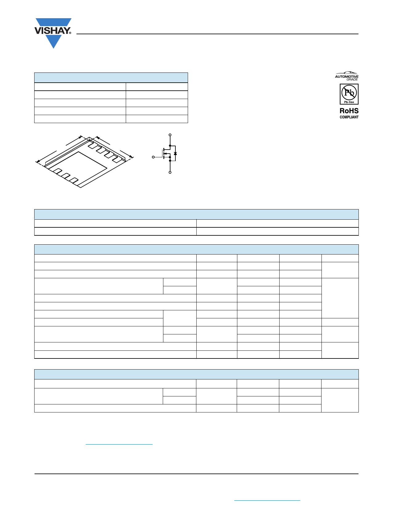
Automotive N-Channel 60 V (D-S) 175 °C MOSFET
PRODUCT SUMMARY
VDS (V)
RDS(on) () at VGS = 10 V
RDS(on) () at VGS = 4.5 V
ID (A)
Configuration
PowerPAK 1212-8
60
0.025
0.036
5.6
Single
D
FEATURES
• TrenchFET® Power MOSFET
• Low Thermal Resistance PowerPAK® 1212-8
Package with 1.07 mm Profile
• PWM Optimized
• AEC-Q101 Qualified
• 100 % Rg and UIS Tested
• Compliant to RoHS Directive 2002/95/EC
3.30 mm
D
8D
7
D
6
D
5
S
1S
3.30 mm
2
S
3G
4
Bottom View
G
S
N-Channel MOSFET
ORDERING INFORMATION
Package
Lead (Pb)-free and Halogen-free
PowerPAK1212-8
SQ7414EN-T1-E3
ABSOLUTE MAXIMUM RATINGS (TC = 25 °C, unless otherwise noted)
PARAMETER
SYMBOL
10 s
Drain-Source Voltage
VDS 60
Gate-Source Voltage
VGS ± 20
Continuous Drain Currenta
Continuous Source Current (Diode Conduction)a
Pulsed Drain Currentb
TC = 25 °C
TC = 70 °C
ID
IS
IDM
8.7
7
3.2
30
Single Pulse Avalanche Current
Single Pulse Avalanche Energy
L = 0.1 mH
IAS
EAS
19
18
Maximum Power Dissipationb
TC = 25 °C
TA = 25 °C
PD
3.8
2
Operating Junction and Storage Temperature Range
Soldering Recommendations (Peak Temperature)d, e
TJ, Tstg
- 55 to + 175
260
STEADY STATE
60
± 20
5.6
4.4
1.3
30
19
18
1.5
0.8
- 55 to + 175
260
UNIT
V
A
mJ
W
°C
THERMAL RESISTANCE RATINGS
PARAMETER
SYMBOL
TYPICAL
MAXIMUM
UNIT
Junction-to-Ambient
t 10 s
PCB Mountc
RthJA
26
65
33
81 °C/W
Junction-to-Case (Drain)
RthJC
1.9
2.4
Notes
a. Package limited.
b. Pulse test; pulse width 300 μs, duty cycle 2 %.
c. When mounted on 1" square PCB (FR-4 material).
d. See solder profile (www.vishay.com/ppg?73257). The PowerPAK 1212-8 is a leadless package. The end of the lead terminal is exposed
copper (not plated) as a result of the singulation process in manufacturing. A solder fillet at the exposed copper tip cannot be guaranteed
and is not required to ensure adequate bottom side solder interconnection.
e. Rework conditions: manual soldering with a soldering iron is not recommended for leadless components.
S11-2129 Rev. D, 31-Oct-11
1
Document Number: 74489
THIS DOCUMENT IS SUBJECT TO CHANGE WITHOUT NOTICE. THE PRODUCTS DESCRIBED HEREIN AND THIS DOCUMENT
ARE SUBJECT TO SPECIFIC DISCLAIMERS, SET FORTH AT www.vishay.com/doc?91000
Datasheet pdf - http://www.DataSheet4U.net/
1 page 
www.DataSheet.co.kr
www.vishay.com
THERMAL RATINGS (TA = 25 °C, unless otherwise noted)
2
1
Duty Cycle = 0.5
SQ7414EN
Vishay Siliconix
0.2
0.1
0.1
0.05
0.02
0.01
10-4
Single Pulse
10-3
Notes:
PDM
10-2
10-1
1
Square Wave Pulse Duration (s)
t1
t2
1. Duty Cycle, D =
t1
t2
2. Per Unit Base = R thJA = 65 °C/W
3. T JM - TA = PDMZthJA(t)
4. Surface Mounted
10 100 600
Normalized Thermal Transient Impedance, Junction-to-Ambient
2
1
Duty Cycle = 0.5
0.2
0.1
0.1 Single Pulse
0.05
0.02
0.01
10-4
10-3
10-2
Square Wave Pulse Duration (s)
10-1
1
Normalized Thermal Transient Impedance, Junction-to-Case
Note
• The characteristics shown in the two graphs
- Normalized Transient Thermal Impedance Junction-to-Ambient (25 °C)
- Normalized Transient Thermal Impedance Junction-to-Case (25 °C)
are given for general guidelines only to enable the user to get a “ball park” indication of part capabilities. The data are extracted from single
pulse transient thermal impedance characteristics which are developed from empirical measurements. The latter is valid for the part
mounted on printed circuit board - FR4, size 1" x 1" x 0.062", double sided with 2 oz. copper, 100 % on both sides. The part capabilities
can widely vary depending on actual application parameters and operating conditions.
Vishay Siliconix maintains worldwide manufacturing capability. Products may be manufactured at one of several qualified locations. Reliability data for Silicon
Technology and Package Reliability represent a composite of all qualified locations. For related documents such as package/tape drawings, part marking, and
reliability data, see www.vishay.com/ppg?74489.
S11-2129 Rev. D, 31-Oct-11
5
Document Number: 74489
THIS DOCUMENT IS SUBJECT TO CHANGE WITHOUT NOTICE. THE PRODUCTS DESCRIBED HEREIN AND THIS DOCUMENT
ARE SUBJECT TO SPECIFIC DISCLAIMERS, SET FORTH AT www.vishay.com/doc?91000
Datasheet pdf - http://www.DataSheet4U.net/
5 Page 
www.DataSheet.co.kr
Application Note 826
Vishay Siliconix
RECOMMENDED MINIMUM PADS FOR PowerPAK® 1212-8 Single
0.016
(0.405)
0.039
(0.990)
0.152
(3.860)
0.068
(1.725)
0.010
(0.255)
0.026
(0.660)
Return to Index
Return to Index
0.025
(0.635)
0.030
(0.760)
Recommended Minimum Pads
Dimensions in Inches/(mm)
Document Number: 72597
Revision: 21-Jan-08
www.vishay.com
7
Datasheet pdf - http://www.DataSheet4U.net/
11 Page | ||
| Páginas | Total 12 Páginas | |
| PDF Descargar | [ Datasheet SQ7414EN.PDF ] | |
Hoja de datos destacado
| Número de pieza | Descripción | Fabricantes |
| SQ7414EN | Automotive N-Channel MOSFET | Vishay |
| Número de pieza | Descripción | Fabricantes |
| SLA6805M | High Voltage 3 phase Motor Driver IC. |
Sanken |
| SDC1742 | 12- and 14-Bit Hybrid Synchro / Resolver-to-Digital Converters. |
Analog Devices |
|
DataSheet.es es una pagina web que funciona como un repositorio de manuales o hoja de datos de muchos de los productos más populares, |
| DataSheet.es | 2020 | Privacy Policy | Contacto | Buscar |