|
|
|
PDF BP5844 Data sheet ( Hoja de datos )
| Número de pieza | BP5844 | |
| Descripción | Isolated High-power LED Driver | |
| Fabricantes | ROHM Semiconductor | |
| Logotipo | ||
Hay una vista previa y un enlace de descarga de BP5844 (archivo pdf) en la parte inferior de esta página. Total 4 Páginas | ||
|
No Preview Available !
Data Sheet
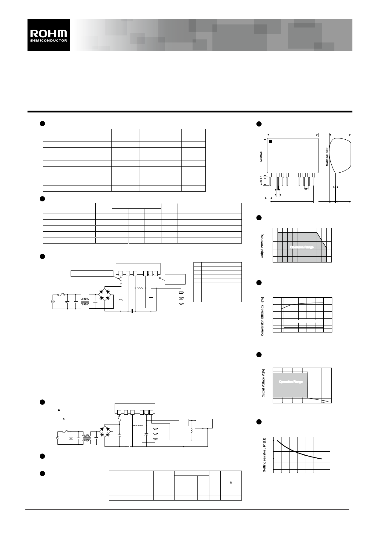
100VAC Input/2.5V-12V (250-360mA) Output
Isolated High-power LED Driver for Illumination
BP5844
Absolute Maximum Ratings
Parameter
Input voltage
Output voltage (limits)
Output voltage (no load)
Output current
Output control terminal voltage
Withstand voltage
Maximum surface temperature
Operating temperature range
Storage temperature range
Symbol
Vi
Vo
Vo
Io
VCTL
BV
Tcmax
Topr
Tstg
Limits
170
12
12.5
378
12.5
1.8
105
-20 to +80
-25 to +85
Units
V
V
V
mA
V
kV
°C
°C
°C
Electrical Characteristics
Parameter
Symbol Min.
Spec
Typ.
Max.
Units
Conditions
Input voltage range
Vi 113 141 170
V-
Output current
Output voltage range
Io 342 360 378 mA Vi=141V,R1=0.78Ω
Vo 2.5 - 12 V Vi=141V,Io=360mA
∗1
Output ripple voltage
Vp -
- 0.5 Vp-p Vi=141V,Io=360mA
∗2
Conversion efficiency
η 80 85 - % Vi=141V,Vo=12V,Io=360mA
∗1 Maximum output current varies depending on ambient temperature. Refer to the derating curve.
∗2 Spike noise is not included in output ripple voltage.
Application Circuit Example
Use a fuse for safety.
AC100V
ZNR1 C3
D1
LF1
C4
BP5844
138
9 10 11
F1
R1
Output control
terminal
+
C1
C5
Pin No.
Terminal name
1 Input terminal (+)
2 Skip
3 Input terminal (-)www.DataSheet.co.kr
4,5 N.C
6-7 Skip
8 Output capacitor connection terminal (-)
9 LED connection terminal (cathode)
10 LED connection terminal (anode)
11 VCTL terminal
Please verify operation and characteristics in the customer's circuit before actual usage.
Ensure that the load current does not exceed the maximum rating.
External Component Specifications
C1 : Input capacitor
C2 : Output capacitor
R1 : Output current setting resistor
C3,C4: Noise reduction capacitor
C5: Noise reduction capacitor
D1: Diode bridge
F1: FUSE
LF1: Line filter
ZNR1: Varistor
10µF / 250V (general purpose)
47µF / 25V low impedance type
0.78Ω(0.22Ω+0.56Ω)±1% 1/4 (Io=360mA)
By changing R1 it is possible to adjust output voltage.
Refer the Output Voltage Setting graph at right
Use if required
adove 125V 0.1 to 0.22µF
2200pF(Products with basic isolation certification)
400V / 1A
Use a fuse for safety.
10mH
A varistor is required to protect against lightning surges
and static electricity.
PWM dimming circuit
VoH 9V PWM dimming by
using the 11pin
VF X n 9V
AC100V
D1
LF1
ZNR1 C3
C4
BP5844
138
9 10 11
F1
R1
+
C1
C5
+
C2
3 Terminal Reg(5V)
IN OUT
COM
Micro
computer
10kΩ
PWM signal
Phase control dimming circuit
PWM dimming is possible by configuring a phase control circuit at the input side.
PWM dimming signal
In case of using PWM or phase
control dimming, please input the
PWM signals at the VCTL pin.
Parameter
LED OFF Voltage
PWM Signal H level
PWM Signal L level
PWM Signal freqency
Symbol
VoL
VCTL(H)
VCTL(L)
fosc
Spec
Min. Typ.
6.5 6.9
35
0-
90 100
Max. Units Conditions
7.3 V VoH 9V
10 V
0.5 V
132 kHz ∗3
∗3 Flickering may occur due to LED load. Please evaluate with the actual application to determine the frequency.
www.rohm.com
©2010 ROHM Co., Ltd. All rights reserved.
1/1
Dimensions (Unit : mm)
33.5MAX.
15.1MAX.
MARKING SIDE
1 345
8 9 10 11
3.9MAX
0.75±0.1
1 . 3 ±0 . 2
2 . 5 4 ±0 . 2
2.54�10=25.4TYP.
4.4MAX.
0 . 5 ±0 . 1
10.7MAX.
Derating Curve
Derating Curve
5
4
3
2 Operation Range
1
0
-30 -20 -10 0 10 20 30 40 50 60 70 80 90
Ambient Temperature Ta(°C)
Output Characteristics
100
90
80
70
60
50
40
30
20
10
0
0.00
CONVERSION EFFICIENCY
(Vi=141V, R1=0.78Ω, Ta=25°C)
Operation Range
2.00 4.00 6.00 8.00 10.00 12.00 14.00
Output Voltage Vo[V]
Load Regulation
14.0
12.0
10.0
8.0
6.0
4.0
2.0
0.0
0
LOAD REGULATION
(Vi=141V, R1=0.78Ω, Ta=25°C)
Operation Range
100 200 300 400 500
Output Current Io[mA]
600
Output voltage setting
Output current-Setting resistor characteristic
2.0
1.8
1.6
1.4
1.2
1.0
0.8
0.6
0.4
0.2
0.00.24 0.26 0.28 0.30 0.32 0.34 0.36 0.38
Output Current(A)
How to calculate setting resistor R1
R1=0.13741/(0.91 x lo-0.151)
lo : Output current
Note) A maximum output current is set to 360mA.
Operation beyond this limit are prohibited.
2010.01 - Rev.A
Datasheet pdf - http://www.DataSheet4U.net/
1 page | ||
| Páginas | Total 4 Páginas | |
| PDF Descargar | [ Datasheet BP5844.PDF ] | |
Hoja de datos destacado
| Número de pieza | Descripción | Fabricantes |
| BP5841 | High-power LED Drivers | ROHM Semiconductor |
| BP5841-1 | High-power LED Drivers | ROHM Semiconductor |
| BP5841A | High-power LED Drivers | ROHM Semiconductor |
| BP5841A1 | High-power LED Drivers | ROHM Semiconductor |
| Número de pieza | Descripción | Fabricantes |
| SLA6805M | High Voltage 3 phase Motor Driver IC. |
Sanken |
| SDC1742 | 12- and 14-Bit Hybrid Synchro / Resolver-to-Digital Converters. |
Analog Devices |
|
DataSheet.es es una pagina web que funciona como un repositorio de manuales o hoja de datos de muchos de los productos más populares, |
| DataSheet.es | 2020 | Privacy Policy | Contacto | Buscar |