|
|
|
PDF BD9161FVM Data sheet ( Hoja de datos )
| Número de pieza | BD9161FVM | |
| Descripción | Synchronous Buck Converter Integrated FET | |
| Fabricantes | ROHM Semiconductor | |
| Logotipo | ||
Hay una vista previa y un enlace de descarga de BD9161FVM (archivo pdf) en la parte inferior de esta página. Total 19 Páginas | ||
|
No Preview Available !
Datasheet
2.5V to 4.5V, 0.6A 1ch
Synchronous Buck Converter Integrated FET
BD9161FVM
●General Description
ROHM’s high efficiency step-down switching regulator
BD9161FVM is a power supply designed to produce
1.2volts (low voltage) from 3.3volts power supply line.
Offers high efficiency with our original pulse skip
control technology and synchronous rectifier.
Employs a current mode control system to provide
faster transient response to sudden change
in load.
●Features
Offers fast transient response with current mode
PWM control system.
Offers highly efficiency for all load range with
synchronous rectifier (Nch/Pch FET)
Incorporates 100% Duty function.
Incorporates soft-start function.
Incorporates thermal protection and ULVO
functions.
Incorporates short-current protection circuit with
time delay function.
Incorporates shutdown function Icc=0μA (Typ.)
●Key Specifications
Input voltage range:
Output voltage range:
Output current:
Switching frequency:
Pch FET ON resistance:
Nch FET ON resistance:
Standby current:
Operating temperature range:
2.5V to 4.5V
1.0V to 3.3V
0.6A(Max.)
1MHz(Typ.)
0.35Ω(Typ.)
0.37Ω(Typ.)
0μA (Typ.)
-25℃ to +85℃
●Package
MSOP8:
2.90 mm x 4.00 mm x 0.83 mm
●Applications
Power supply for HDD, DVD and for LSI of CPU, ASIC
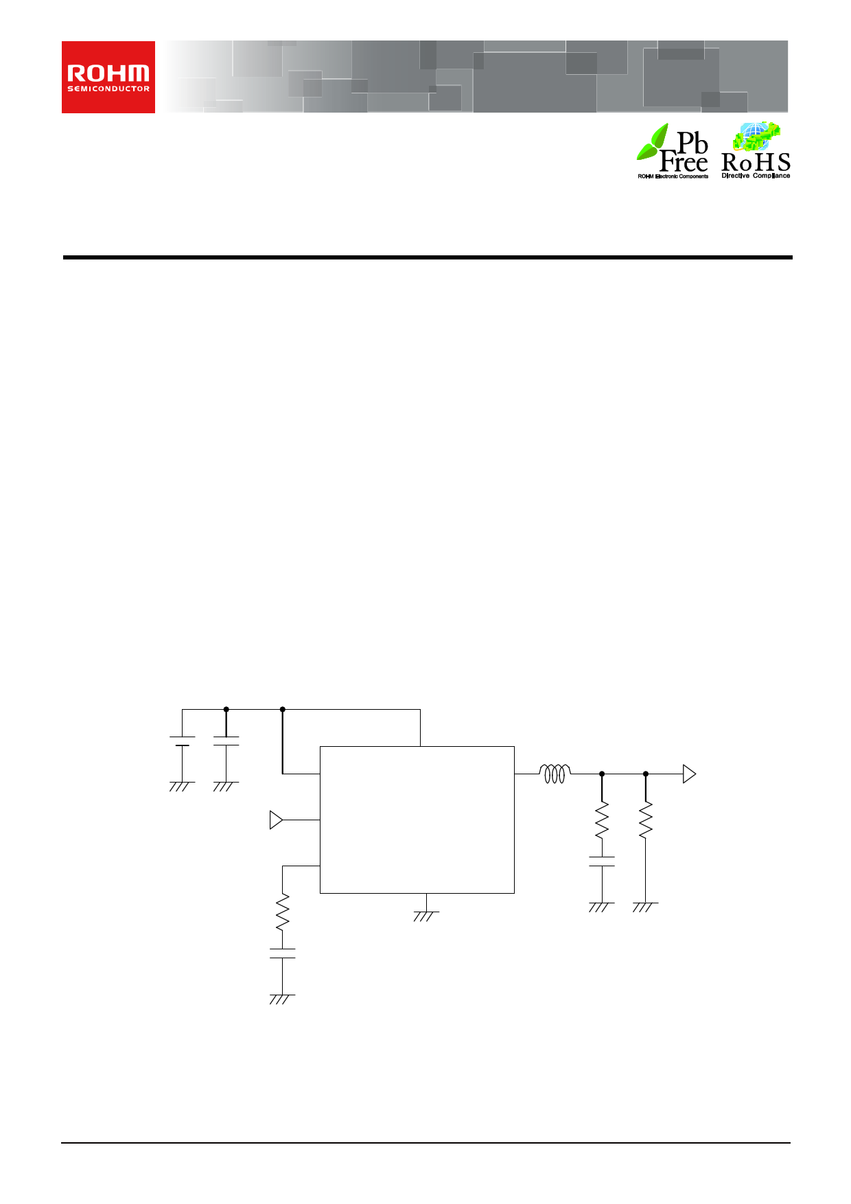
●Typical Application Circuit
www.DataSheet.co.kr
VCC
Cin
VOUT
RITH
CITH
VCC,PVCC
EN SW
VOUT
ITH
GND,PGND
L
ESR
CO
VOUT
RO
Fig.1 Typical application circuit
○Product structure:Silicon monolithic integrated circuit
www.rohm.com
© 2011 ROHM Co., Ltd. All rights reserved.
TSZ22111・14・001
○This product is not designed protection against radioactive rays.
1/17
TSZ02201-0J3J0AJ00190-1-2
02.MAR.2012 Rev.001
Datasheet pdf - http://www.DataSheet4U.net/
1 page 
BD9161FVM
Datasheet
Fig.8 Efficiency
Fig.9 Ta - Fosc
www.DataSheet.co.kr
Fig.10 Ta-VEN
Fig.11 Ta-ICC
www.rohm.com
© 2011 ROHM Co., Ltd. All rights reserved.
TSZ22111・15・001
5/17
TSZ02201-0J3J0AJ00190-1-2
02.MAR.2012 Rev.001
Datasheet pdf - http://www.DataSheet4U.net/
5 Page 
BD9161FVM
Datasheet
Switching Regulator Efficiency
Efficiency ŋ may be expressed by the equation shown below:
η= VOUT×IOUT ×100[%]= POUT ×100[%]=
POUT ×100[%]
Vin×Iin
Pin POUT+PDα
Efficiency may be improved by reducing the switching regulator power dissipation factors PDα as follows:
Dissipation factors:
1) ON resistance dissipation of inductor and FET:PD(I2R)
2) Gate charge/discharge dissipation:PD(Gate)
3) Switching dissipation:PD(SW)
4) ESR dissipation of capacitor:PD(ESR)
5) Operating current dissipation of IC:PD(IC)
1)PD(I2R)=IOUT2×(RCOIL+RON) (RCOIL[Ω]:DC resistance of inductor, RON[Ω]:ON resistance of FET
IOUT[A]:Output current.)
2)PD(Gate)=Cgs×f×V (Cgs[F]:Gate capacitance of FET, f[H]:Switching frequency, V[V]:Gate driving voltage of FET)
Vin2×CRSS×IOUT×f
3)PD(SW)=
IDRIVE
(CRSS[F]:Reverse transfer capacitance of FET, IDRIVE[A]:Peak current of gate.)
4)PD(ESR)=IRMS2×ESR (IRMS[A]:Ripple current of capacitor, ESR[Ω]:Equivalent series resistance.)
5)PD(IC)=Vin×ICC (ICC[A]:Circuit current.)
Consideration on Permissible Dissipation and Heat Generation
As this IC functions with high efficiency without significant heat generation in most applications, no special consideration is
needed on permissible dissipation or heat generation. In case of extreme conditions, however, including lower input
voltage, higher output voltage, heavier load, and/or higher temperature, the permissible dissipation and/or heat generation
must be carefully considered.
For dissipation, only conduction losses due to DC resistance of inductor and ON resistance of FET are considered.
Because the conduction losses are considered to play the leading role among other dissipation mentioned above including
gate charge/discharge dissipation and switching dissipation.
1000
800
②587.4mW
600
①387.5mW
400
①Using an IC alone
θj-a=322.6℃/W
②mounted on glass epoxy PCB
θj-a=212.8℃/W
P=IOUT2×(RON)
RON=D×RONP+(1-D)×RONN
D:ON duty (=V /V )www.DataSheet.co.kr
OUT
CC
RONP:ON resistance of P-channel MOS FET
RONN:ON resistance of N-channel MOS FET
IOUT:Output current
200
0
0 25 50 75 85 100 125 150
Ambient temperature:Ta [℃]
Fig.27 Thermal derating curve
(MSOP8)
If VCC=3.3V, VOUT=2.5V RONP=0.35Ω, RONN=0.37Ω
IOUT=0.6A, for example,
D=VOUT/VCC=2.5/3.3=0.758
RON=0.758×0.35+(1-0.758)×0.37
=0.2653+0.08954
=0.35484[Ω]
P=0.62×0.35484
≒127.7[mV]
As RONP is greater than RONN in this IC, the dissipation increases as the ON duty becomes greater. With the consideration
on the dissipation as above, thermal design must be carried out with sufficient margin allowed.
www.rohm.com
© 2011 ROHM Co., Ltd. All rights reserved.
TSZ22111・15・001
11/17
TSZ02201-0J3J0AJ00190-1-2
02.MAR.2012 Rev.001
Datasheet pdf - http://www.DataSheet4U.net/
11 Page | ||
| Páginas | Total 19 Páginas | |
| PDF Descargar | [ Datasheet BD9161FVM.PDF ] | |
Hoja de datos destacado
| Número de pieza | Descripción | Fabricantes |
| BD9161FVM | Synchronous Buck Converter Integrated FET | ROHM Semiconductor |
| Número de pieza | Descripción | Fabricantes |
| SLA6805M | High Voltage 3 phase Motor Driver IC. |
Sanken |
| SDC1742 | 12- and 14-Bit Hybrid Synchro / Resolver-to-Digital Converters. |
Analog Devices |
|
DataSheet.es es una pagina web que funciona como un repositorio de manuales o hoja de datos de muchos de los productos más populares, |
| DataSheet.es | 2020 | Privacy Policy | Contacto | Buscar |