|
|
|
PDF CS1630 Data sheet ( Hoja de datos )
| Número de pieza | CS1630 | |
| Descripción | (CS1630 / CS1631) 2-Channel TRIAC Dimmable LED Driver IC | |
| Fabricantes | Cirrus Logic | |
| Logotipo | ||
Hay una vista previa y un enlace de descarga de CS1630 (archivo pdf) en la parte inferior de esta página. Total 30 Páginas | ||
|
No Preview Available !
CS1630
CS1631
2-Channel TRIAC Dimmable LED Driver IC
Features & Description
• Best-in-class Dimmer Compatibility
- Leading-edge (TRIAC) Dimmers
- Trailing-edge Dimmers
- Digital Dimmers (with Integrated Power Supply)
• Correlated Color Temperature (CCT) Control System
• Up to 85% Efficiency
• Flicker-free Dimming
• Programmable Dimming Profile
- Constant CCT Dimming
- Black Body Line Dimming
• 0% Minimum Dimming Level
• Temperature Compensated LED Current
• End-of-line Programming Using Power Line Calibration
- Lower LED Binning Requirement
• Programmable Series or Parallel 2-Channel Output
- Interleaved Output Eliminates Additional Transformer
• Programmable Quasi-resonant Second Stage with
Constant-current Output
- Flyback, Buck, and Tapped Buck
• Register Lockout
• Fast Startup
• Tight LED Current Regulation: Better than ±5%
• Primary-side Regulation (PSR)
• >0.9 Power Factor
• IEC-61000-3-2 Compliant
• Soft Start
• Protections:
- Output Open/Short
- Current-sense Resistor Open/Short
- External Overtemperature Using NTC
Overview
The CS1630 and CS1631 are high-performance offline AC /DC
LED drivers for dimmable and high color rendering index (CRI)
LED replacement lamps and luminaires. It features Cirrus Logic’s
proprietary digital dimmer compatibility control technology and
digital correlated color temperature (CCT) control system that
enables two-channel LED color mixing. The CS1630 is designed
for 120VAC line voltage applications, and the CS1631 is
optimized for 230VAC line voltage applications.
The CS1630/31 integrates a critical conduction mode boost
converter, providing power factor correction and superior dimmer
compatibility with a primary-side regulated quasi-resonant second
stage, which is configurable for isolated and non-isolated
topologies. The digital CCT control system provides the ability to
program dimming profiles, such as constant CCT dimming and
black body line dimming. The CS1630/31 optimizes LED color
mixing by temperature compensating LED current with an
external NTC. The IC controller is also equipped with power line
calibration for remote system calibration and end-of-line
programming. The CS1630/31 provides a register lockout feature
for security against potential access to proprietary registers.
Applications & Description
• Dimmable Retrofit LED Lamps and LED Luminaries
• High CRI Lighting
• Offline LED Drivers
• Commercial Lighting
Ordering Information
See page 53.
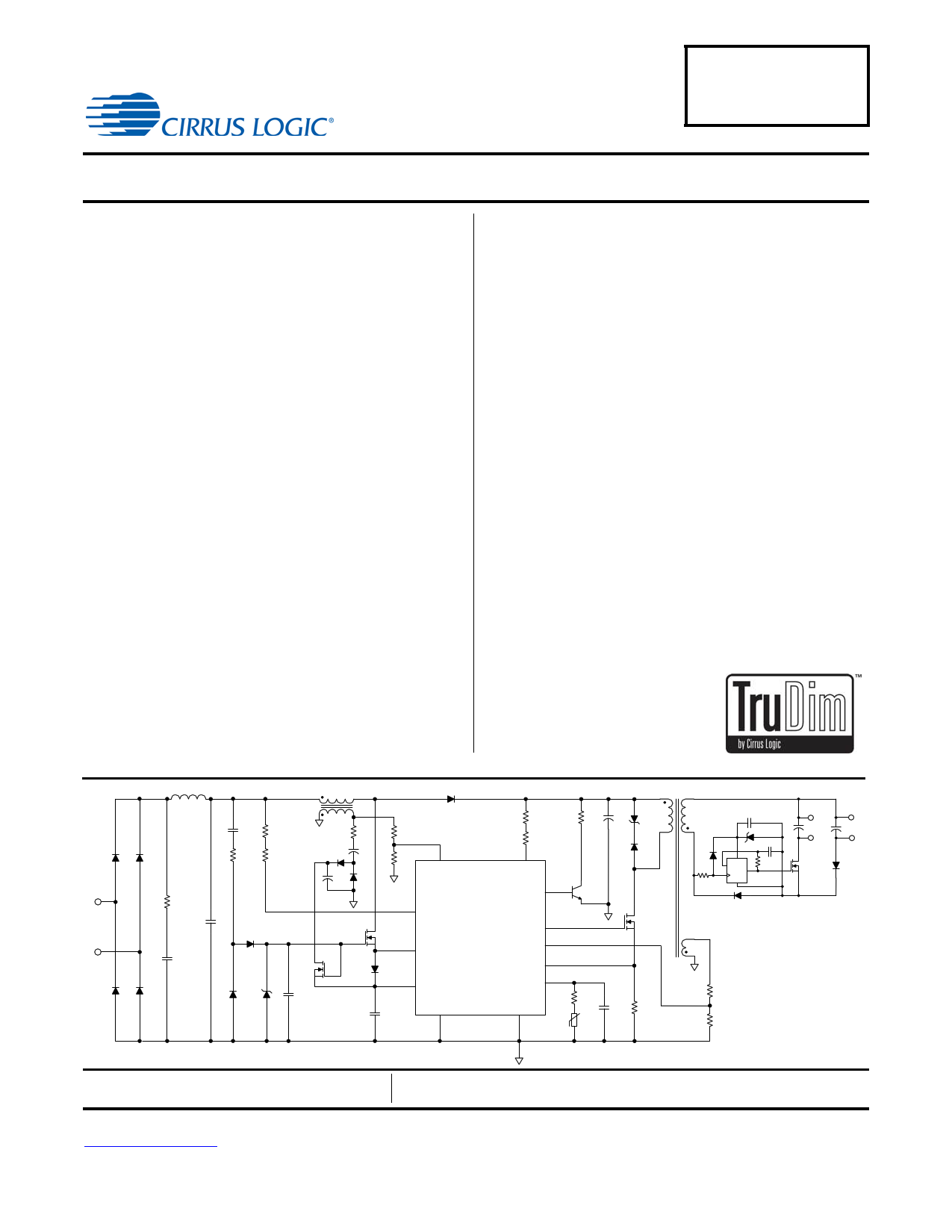
L1
BR1 BR1
AC
Mains
BR1
R1
C2
C1
BR1
Vr ec t
C3 R3
R2 R4
D2
Q1
D1 Z1 C4
L2
R5
D3 C6
C5 D4
D6
R6
R7 1
BSTAUX
R8
R9
16
BSTOUT
CLAMP 3
2
IAC
CS1630 /31
13
GD
Q2 15
5 FBAUX
SOURCE
D5 FBSENSE 11
14 VDD
10
eOTP
C7 SGND
4
GND
12
VB S T
R10 C8 Z2
D7
Q3
Q4
T1
D8
R12
C9
Z3
C10
V CC
D_
Q
GND
R15
D9
RS
NTC
CNTC R11
R13
R14
LED2+
C11
LED 2-
Q5
LED1+
C12
LED 1-
D10
Preliminary Product Information
This document contains information for a product under development.
Cirrus Logic reserves the right to modify this product without notice.
Cirrus Logic, Inc.
http://www.cirrus.com
Copyright Cirrus Logic, Inc. 2012
(All Rights Reserved)
MAY’12
DS954PP4
1 page 
CS1630/31
Parameter
Second Stage Pulse Width Modulator
Minimum Switching Frequency
Maximum Switching Frequency
Second Stage Gate Driver
Output Source Resistance
Output Sink Resistance
Rise Time
Fall Time
(Note 5)
(Note 5)
Second Stage Protection
Overcurrent Protection (OCP)
Overvoltage Protection (OVP)
Open Loop Protection (OLP)
External Overtemperature Protection (eOTP)
Pull-up Current Source – Maximum
Conductance Accuracy
(Note 3)
Conductance Offset
(Note 3)
Current Source Voltage Threshold
Internal Overtemperature Protection (iOTP)
Thermal Shutdown Threshold
(Note 4)
Thermal Shutdown Hysteresis (Note 4)
Condition
VDD = 12V
VDD = 12V
CL = 0.25nF
CL = 0.25nF
Symbol
Min
tFB(Min)
tFB(Max)
-
-
-
-
-
-
VOCP(th)
VOVP(th)
VOLP(th)
ICONNECT
VCONNECT(th)
TSD
TSD(Hy)
-
-
-
-
-
-
-
-
-
Typ
625
200
24
11
-
-
1.69
1.25
200
80
-
± 250
1.25
135
14
Max Unit
- Hz
- kHz
-
-
30 ns
20 ns
-V
-V
- mV
- A
±5
- nS
-V
- ºC
- ºC
Notes:
1.
The CS1630/31 has an internal shunt
in the VDD Supply Voltage section on
regulator
page 4.
that
limits
the
voltage
on
the
VDD
pin.
VZ,
the
shunt
regulation
voltage,
is
defined
2. External circuitry should be designed to ensure that the ZCD current drawn from the internal clamp diode when it is forward biased
does not exceed specification.
3. Conductance is the inverse of resistance (1/) and is expressed in siemens (S). A decrease in conductance is equivalent to an
increase in resistance.
4. Specifications are guaranteed by design and are characterized and correlated using statistical process methods.
5. For test purposes, load capacitance (CL) is 0.25nF and is connected as shown in the following diagram.
VDD
VDD
GD
S1
R1
GND
CS
CL
0.25nF
+15V
Buffer
TP
R2 -15V
R3
GD OUT
S2
DS954PP4
5
5 Page 
CS1630/31
5.3.4 Leading-edge Mode
In Leading-edge Mode, the CS1630/31 regulates the boost
output voltage (VBST) while maintaining the dimmer phase
angle (see Figure 9). The device executes a CCM boost
algorithm using dimmer attach current as the initial peak current
for the initial firing event of the dimmer. Upon gaining control of
the incoming current, the CS1630/31 transitions to a CRM
boost algorithm to regulate the boost output voltage. The device
periodically executes a probe event on the incoming waveform.
The information from the probe event is used to maintain proper
operation with the dimmer circuitry.
Figure 9. Leading-edge Mode Phase-cut Waveform
5.3.5 Trailing-edge Mode
In Trailing-edge Mode, the CS1630/31 determines its operation
based on the falling edge of the input voltage waveform (see
Figure 10). To provide proper dimmer operation, the
CS1630/31 executes the boost algorithm on the falling edge of
the input line voltage that maintains a charge in the dimmer
capacitor. To ensure maximum compatibility with dimmer
components, the device boosts during this falling edge event
using a peak current that must meet a minimum value. In
Trailing-edge Mode, only the CRM boost algorithm is used.
5.4 Correlated Color Temperature Control
The CS1630/31 color control system can adjust and maintain
the correlated color temperature (CCT) for the LED color
mixing application by connecting an external negative
temperature coefficient (NTC) thermistor to the eOTP pin. The
LED temperature variation can be accurately detected by the
internal eOTP feedback loops (see "External Overtemperature
Protection" on page 17).
Red and amber LEDs are necessary components in color-
mixing applications when providing warm white or other CCTs.
When mixing colors, red and amber LEDs are the most
temperature sensitive, so they cause a large variation in
temperature. The CS1630/31 is capable of providing LED
CCT and luminosity with temperature compensation using the
NTC thermistor to resolve the significant change in the
luminous output due to temperature variations.
Since LED lumens are mainly a function of temperature and
forward current, color temperature and luminosity can be
maintained by independently adjusting each string's output
current as the ambient temperature changes. This can be
done by mapping the NTC reading to a required value of the
current in each string using a digital mapping block.
In the CS1630/31, only one of the LED string currents is
compensated for due to temperature variations. The current in
the other string is kept constant over temperature, which may
result in the luminosity decreasing slightly as temperature
increases. In order for the ADC to resolve the entire range of
possible temperature variation in the LEDs, it is recommended
to select a series resistor (RS) and an NTC (RNTC) with the
appropriate Beta value, which retains the total resistance
(RS+RNTC) at all possible operating temperatures within the
tracking range of the ADC. The final temperature to digital
code mapping depends on these variables.
The CS1630/31 color control system also has the ability to
maintain a constant CCT or change CCT as the light dims.
OTP configurations allow the selection of the dimming profile.
A specific CCT profile can be programmed to the digital
mapping device. In this case, the mapping is two-dimensional:
one current versus temperature profile is generated for each
dim level. The CS1630/31 provides two-dimensional mapping
for the color LED’s current only, and one-dimensional
mapping (current versus dim level) for the other string. A
simplified block diagram of the color control system is shown
in Figure 11.
Figure 10. Trailing-edge Mode Phase-cut Waveform
DS954PP4
11
11 Page | ||
| Páginas | Total 30 Páginas | |
| PDF Descargar | [ Datasheet CS1630.PDF ] | |
Hoja de datos destacado
| Número de pieza | Descripción | Fabricantes |
| CS1630 | (CS1630 / CS1631) 2-Channel TRIAC Dimmable LED Driver IC | Cirrus Logic |
| CS1631 | (CS1630 / CS1631) 2-Channel TRIAC Dimmable LED Driver IC | Cirrus Logic |
| CS16312EN | VFD Display driving circuit | Semico |
| Número de pieza | Descripción | Fabricantes |
| SLA6805M | High Voltage 3 phase Motor Driver IC. |
Sanken |
| SDC1742 | 12- and 14-Bit Hybrid Synchro / Resolver-to-Digital Converters. |
Analog Devices |
|
DataSheet.es es una pagina web que funciona como un repositorio de manuales o hoja de datos de muchos de los productos más populares, |
| DataSheet.es | 2020 | Privacy Policy | Contacto | Buscar |