|
|
|
PDF ZL8101 Data sheet ( Hoja de datos )
| Número de pieza | ZL8101 | |
| Descripción | Adaptive Digital DC/DC PWM Controller | |
| Fabricantes | Xicor | |
| Logotipo | ||
Hay una vista previa y un enlace de descarga de ZL8101 (archivo pdf) en la parte inferior de esta página. Total 36 Páginas | ||
|
No Preview Available !
Adaptive Digital DC/DC PWM Controller with Auto
Compensation
ZL8101
The ZL8101 is a digital PWM controller with auto
compensation that is designed to work with either the ZL1505
MOSFET driver IC, ISL6611 Phase Doubler IC, or DrMOS type
devices. Current sharing allows multiple devices to be
connected in parallel to source loads with very high current
demands. Adaptive performance optimization algorithms
improve power conversion efficiency across the entire load
range. Zilker Labs Digital-DC™ technology enables a blend of
power conversion performance and power management
features.
The ZL8101 is designed to be a flexible building block for DC
power and can be easily adapted to designs ranging from a
single-phase power supply operating from a 4.5V input to a
multi-phase supply operating from a 12V input. The ZL8101
eliminates the need for complicated power supply managers
as well as numerous external discrete components.
Most operating features can be configured by simple
pin-strap/resistor selection or through the SMBus™ serial
interface. The ZL8101 uses the PMBus™ protocol for
communication with a host controller and the Digital-DC bus
for communication between other Zilker Labs devices.
Features
• Efficient Synchronous Buck Controller
• Adaptive Performance Optimization Algorithms
• ±1% Output Voltage Accuracy
• Auto Compensation
• Snapshot™ Parametric Capture
• I2C/SMBus Interface, PMBus Compatible
• Internal Non-Volatile Memory (NVM)
• Tri-State PWM Gate Outputs
• Compatible with Industry Standard DrMOS Devices
• Compatible with Intersil ISL6611 Phase Doubler
• Synchronized External Driver Control
Applications
• Servers/Storage Equipment
• Telecom/Datacom Equipment
• Power Supplies (Memory, DSP, ASIC, FPGA)
Related Literature
• AN2033 “Zilker Labs PMBus Command Set - DDC Products”
www.DataSheet.net/
• AN2034 “Configuring Current Sharing on the ZL2004 and
ZL2006”
• AN2010 “Thermal and Layout Guidelines for Digital-DC™
Products”
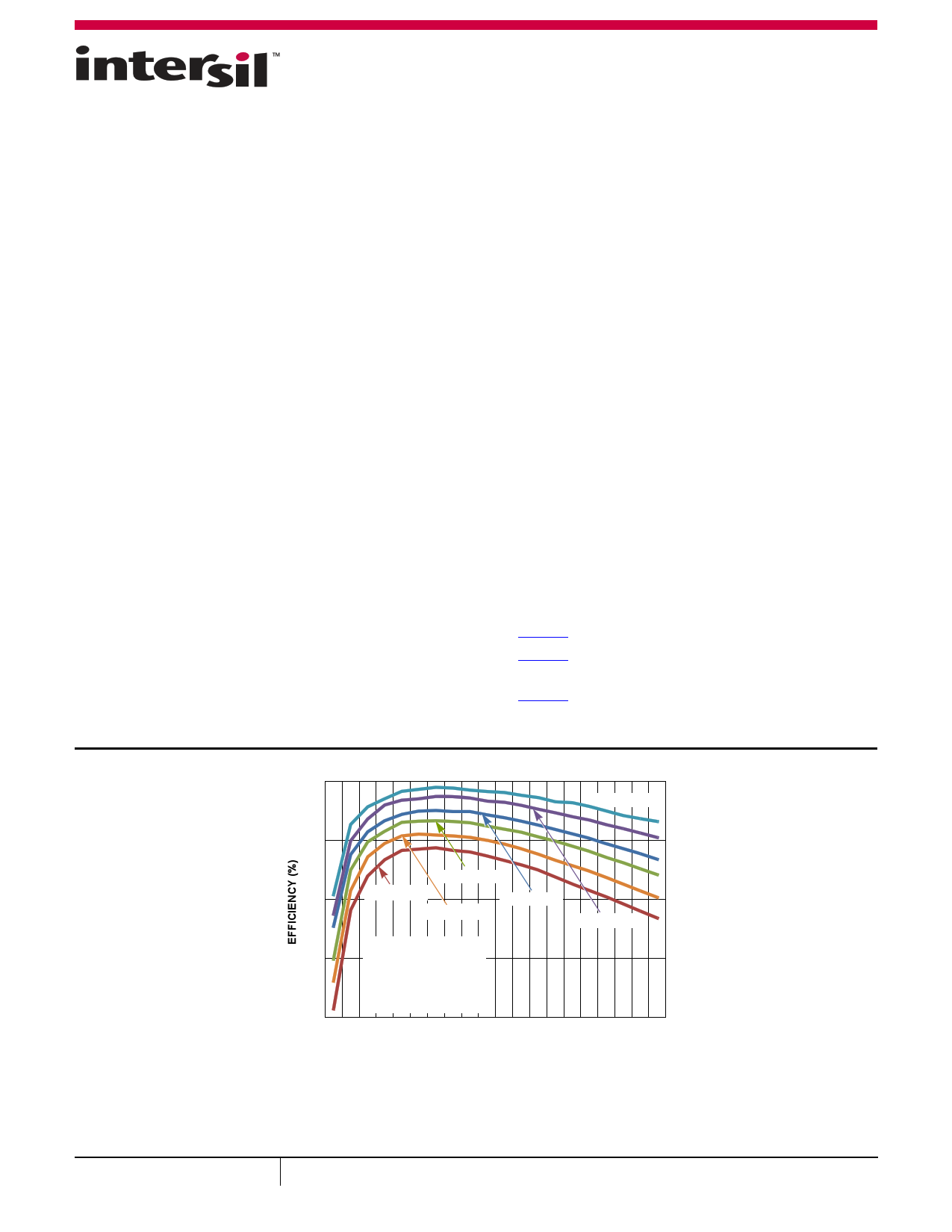
96
VOUT = 3.3V
91
VOUT = 1.5V
86 VOUT = 1.0V
VOUT = 1.8V
VOUT = 1.2V
VOUT = 2.5V
VIN = 12V
81 fSW = 400kHz
L = 0.45µH
GH = 1 x BSC050NE2Ls
GL = 2 x BSC010NE2LS
76
2 4 6 8 10 12 14 16 18 20 22 24 26 28 30 32 34 36 38 40
OUTPUT CURRENT (A)
FIGURE 1. EFFICIENCY vs LOAD CURRENT
July 13, 2012
FN7832.1
1
CAUTION: These devices are sensitive to electrostatic discharge; follow proper IC Handling Procedures.
1-888-INTERSIL or 1-888-468-3774 | Copyright Intersil Americas Inc. 2011, 2012. All Rights Reserved
Intersil (and design) is a trademark owned by Intersil Corporation or one of its subsidiaries.
All other trademarks mentioned are the property of their respective owners.
Datasheet pdf - http://www.DataSheet4U.co.kr/
1 page 
ZL8101
Table of Contents
Absolute Maximum Ratings . . . . . . . . . . . . . . . . . . . . . . . . . . . . . . . . . . . . . . . . . . . . . . . . . . . . . . . . . . . . . . . . . . . . . . . . . . . . . . . . . . . 6
Thermal Information . . . . . . . . . . . . . . . . . . . . . . . . . . . . . . . . . . . . . . . . . . . . . . . . . . . . . . . . . . . . . . . . . . . . . . . . . . . . . . . . . . . . . . . . . 6
Recommended Operating Conditions . . . . . . . . . . . . . . . . . . . . . . . . . . . . . . . . . . . . . . . . . . . . . . . . . . . . . . . . . . . . . . . . . . . . . . . . . . 6
Electrical Specifications . . . . . . . . . . . . . . . . . . . . . . . . . . . . . . . . . . . . . . . . . . . . . . . . . . . . . . . . . . . . . . . . . . . . . . . . . . . . . . . . . . . . . 6
Typical Application Circuit . . . . . . . . . . . . . . . . . . . . . . . . . . . . . . . . . . . . . . . . . . . . . . . . . . . . . . . . . . . . . . . . . . . . . . . . . . . . . . . . . . . 11
ZL8101 Overview . . . . . . . . . . . . . . . . . . . . . . . . . . . . . . . . . . . . . . . . . . . . . . . . . . . . . . . . . . . . . . . . . . . . . . . . . . . . . . . . . . . . . . . . . . . 11
Digital-DC Architecture . . . . . . . . . . . . . . . . . . . . . . . . . . . . . . . . . . . . . . . . . . . . . . . . . . . . . . . . . . . . . . . . . . . . . . . . . . . . . . . . . . . . . . . . . . . 11
Power Conversion Overview . . . . . . . . . . . . . . . . . . . . . . . . . . . . . . . . . . . . . . . . . . . . . . . . . . . . . . . . . . . . . . . . . . . . . . . . . . . . . . . . . . . . . . . 12
Power Management Overview . . . . . . . . . . . . . . . . . . . . . . . . . . . . . . . . . . . . . . . . . . . . . . . . . . . . . . . . . . . . . . . . . . . . . . . . . . . . . . . . . . . . . 12
Multi-mode Pins . . . . . . . . . . . . . . . . . . . . . . . . . . . . . . . . . . . . . . . . . . . . . . . . . . . . . . . . . . . . . . . . . . . . . . . . . . . . . . . . . . . . . . . . . . . . . . . . . 12
Power Conversion Functional Description. . . . . . . . . . . . . . . . . . . . . . . . . . . . . . . . . . . . . . . . . . . . . . . . . . . . . . . . . . . . . . . . . . . . . . 13
Internal Bias Regulators and Input Supply Connections . . . . . . . . . . . . . . . . . . . . . . . . . . . . . . . . . . . . . . . . . . . . . . . . . . . . . . . . . . . . . . . 13
Output Voltage Selection . . . . . . . . . . . . . . . . . . . . . . . . . . . . . . . . . . . . . . . . . . . . . . . . . . . . . . . . . . . . . . . . . . . . . . . . . . . . . . . . . . . . . . . . . 13
Start-up Procedure. . . . . . . . . . . . . . . . . . . . . . . . . . . . . . . . . . . . . . . . . . . . . . . . . . . . . . . . . . . . . . . . . . . . . . . . . . . . . . . . . . . . . . . . . . . . . . . 15
Soft-start Delay and Ramp Times . . . . . . . . . . . . . . . . . . . . . . . . . . . . . . . . . . . . . . . . . . . . . . . . . . . . . . . . . . . . . . . . . . . . . . . . . . . . . . . . . . 15
Power-Good . . . . . . . . . . . . . . . . . . . . . . . . . . . . . . . . . . . . . . . . . . . . . . . . . . . . . . . . . . . . . . . . . . . . . . . . . . . . . . . . . . . . . . . . . . . . . . . . . . . . 16
Switching Frequency and PLL . . . . . . . . . . . . . . . . . . . . . . . . . . . . . . . . . . . . . . . . . . . . . . . . . . . . . . . . . . . . . . . . . . . . . . . . . . . . . . . . . . . . . 16
Power Train Component Selection . . . . . . . . . . . . . . . . . . . . . . . . . . . . . . . . . . . . . . . . . . . . . . . . . . . . . . . . . . . . . . . . . . . . . . . . . . . . . . . . . 18
Current Limit Threshold Selection . . . . . . . . . . . . . . . . . . . . . . . . . . . . . . . . . . . . . . . . . . . . . . . . . . . . . . . . . . . . . . . . . . . . . . . . . . . . . . . . . . 20
Loop Compensation . . . . . . . . . . . . . . . . . . . . . . . . . . . . . . . . . . . . . . . . . . . . . . . . . . . . . . . . . . . . . . . . . . . . . . . . . . . . . . . . . . . . . . . . . . . . . 21
Non-linear Response (NLR) Settings . . . . . . . . . . . . . . . . . . . . . . . . . . . . . . . . . . . . . . . . . . . . . . . . . . . . . . . . . . . . . . . . . . . . . . . . . . . . . . . . 22
Efficiency Optimized Driver Dead-time Control . . . . . . . . . . . . . . . . . . . . . . . . . . . . . . . . . . . . . . . . . . . . . . . . . . . . . . . . . . . . . . . . . . . . . . . 22
Adaptive Diode Emulation . . . . . . . . . . . . . . . . . . . . . . . . . . . . . . . . . . . . . . . . . . . . . . . . . . . . . . . . . . . . . . . . . . . . . . . . . . . . . . . . . . . . . . . . 24
Power Management Functional Description. . . . . . . . . . . . . . . . . . . . . . . . . . . . . . . . . . . . . . . . . . . . . . . . . . . . . . . . . . . . . . . . . . . . . . . . . . . . 24
Input Undervoltage Lockout . . . . . . . . . . . . . . . . . . . . . . . . . . . . . . . . . . . . . . . . . . . . . . . . . . . . . . . . . . . . . . . . . . . . . . . . . . . . . . . . . . . . . . . 24
Output Overvoltage Protection. . . . . . . . . . . . . . . . . . . . . . . . . . . . . . . . . . . . . . . . . . . . . . . . . . . . . . . . . . . . . . . . . . . . . . . . . . . . . . . . . . . . . 24
Output Pre-Bias Protection . . . . . . . . . . . . . . . . . . . . . . . . . . . . . . . . . . . . . . . . . . . . . . . . . . . . . . . . . . . . . . . . . . . . . . . . . . . . . . . . . . . . . . . . 24
Minimum Duty Cycle . . . . . . . . . . . . . . . . . . . . . . . . . . . . . . . . . . . . . . . . . . . . . . . . . . . . . . . . . . . . . . . . . . . . . . . . . . . . . . . . . . . . . . . . . . . . . 24
www.DataSheet.net/
Output Overcurrent Protection . . . . . . . . . . . . . . . . . . . . . . . . . . . . . . . . . . . . . . . . . . . . . . . . . . . . . . . . . . . . . . . . . . . . . . . . . . . . . . . . . . . . . 25
Thermal Overload Protection . . . . . . . . . . . . . . . . . . . . . . . . . . . . . . . . . . . . . . . . . . . . . . . . . . . . . . . . . . . . . . . . . . . . . . . . . . . . . . . . . . . . . . 25
Voltage Tracking . . . . . . . . . . . . . . . . . . . . . . . . . . . . . . . . . . . . . . . . . . . . . . . . . . . . . . . . . . . . . . . . . . . . . . . . . . . . . . . . . . . . . . . . . . . . . . . . 26
Tracking with Autocomp Enabled . . . . . . . . . . . . . . . . . . . . . . . . . . . . . . . . . . . . . . . . . . . . . . . . . . . . . . . . . . . . . . . . . . . . . . . . . . . . . . . . . . 27
Current Sharing and Tracking . . . . . . . . . . . . . . . . . . . . . . . . . . . . . . . . . . . . . . . . . . . . . . . . . . . . . . . . . . . . . . . . . . . . . . . . . . . . . . . . . . . . . 27
Configuring Tracking Groups . . . . . . . . . . . . . . . . . . . . . . . . . . . . . . . . . . . . . . . . . . . . . . . . . . . . . . . . . . . . . . . . . . . . . . . . . . . . . . . . . . . . . . 27
Voltage Margining . . . . . . . . . . . . . . . . . . . . . . . . . . . . . . . . . . . . . . . . . . . . . . . . . . . . . . . . . . . . . . . . . . . . . . . . . . . . . . . . . . . . . . . . . . . . . . . 28
External Voltage Monitoring . . . . . . . . . . . . . . . . . . . . . . . . . . . . . . . . . . . . . . . . . . . . . . . . . . . . . . . . . . . . . . . . . . . . . . . . . . . . . . . . . . . . . . . 28
I2C/SMBus Communications. . . . . . . . . . . . . . . . . . . . . . . . . . . . . . . . . . . . . . . . . . . . . . . . . . . . . . . . . . . . . . . . . . . . . . . . . . . . . . . . . . . . . . 28
I2C/SMBus Device Address Selection. . . . . . . . . . . . . . . . . . . . . . . . . . . . . . . . . . . . . . . . . . . . . . . . . . . . . . . . . . . . . . . . . . . . . . . . . . . . . . . 28
Digital-DC Bus . . . . . . . . . . . . . . . . . . . . . . . . . . . . . . . . . . . . . . . . . . . . . . . . . . . . . . . . . . . . . . . . . . . . . . . . . . . . . . . . . . . . . . . . . . . . . . . . . . 30
Phase Spreading . . . . . . . . . . . . . . . . . . . . . . . . . . . . . . . . . . . . . . . . . . . . . . . . . . . . . . . . . . . . . . . . . . . . . . . . . . . . . . . . . . . . . . . . . . . . . . . . 30
Output Sequencing . . . . . . . . . . . . . . . . . . . . . . . . . . . . . . . . . . . . . . . . . . . . . . . . . . . . . . . . . . . . . . . . . . . . . . . . . . . . . . . . . . . . . . . . . . . . . . 30
Fault Spreading . . . . . . . . . . . . . . . . . . . . . . . . . . . . . . . . . . . . . . . . . . . . . . . . . . . . . . . . . . . . . . . . . . . . . . . . . . . . . . . . . . . . . . . . . . . . . . . . . 31
Active Current Sharing . . . . . . . . . . . . . . . . . . . . . . . . . . . . . . . . . . . . . . . . . . . . . . . . . . . . . . . . . . . . . . . . . . . . . . . . . . . . . . . . . . . . . . . . . . . 31
Turn-On/Off Ramp Behavior. . . . . . . . . . . . . . . . . . . . . . . . . . . . . . . . . . . . . . . . . . . . . . . . . . . . . . . . . . . . . . . . . . . . . . . . . . . . . . . . . . . . . . . 32
Current Share Fault Behavior . . . . . . . . . . . . . . . . . . . . . . . . . . . . . . . . . . . . . . . . . . . . . . . . . . . . . . . . . . . . . . . . . . . . . . . . . . . . . . . . . . . . . . 32
Phase Adding/Dropping . . . . . . . . . . . . . . . . . . . . . . . . . . . . . . . . . . . . . . . . . . . . . . . . . . . . . . . . . . . . . . . . . . . . . . . . . . . . . . . . . . . . . . . . . . 32
Monitoring Via I2C/SMBus . . . . . . . . . . . . . . . . . . . . . . . . . . . . . . . . . . . . . . . . . . . . . . . . . . . . . . . . . . . . . . . . . . . . . . . . . . . . . . . . . . . . . . . . 32
Temperature Monitoring Using the XTEMP Pin . . . . . . . . . . . . . . . . . . . . . . . . . . . . . . . . . . . . . . . . . . . . . . . . . . . . . . . . . . . . . . . . . . . . . . . 33
Snapshot™ Parameter Capture . . . . . . . . . . . . . . . . . . . . . . . . . . . . . . . . . . . . . . . . . . . . . . . . . . . . . . . . . . . . . . . . . . . . . . . . . . . . . . . . . . . . 33
Non-Volatile Memory and Device Security Features . . . . . . . . . . . . . . . . . . . . . . . . . . . . . . . . . . . . . . . . . . . . . . . . . . . . . . . . . . . . . . . . . . . 33
Configuration Files. . . . . . . . . . . . . . . . . . . . . . . . . . . . . . . . . . . . . . . . . . . . . . . . . . . . . . . . . . . . . . . . . . . . . . . . . . . . . . . . . . . . . . . . . . . . . . . 34
Programmable Gain Amplifier Bias Current. . . . . . . . . . . . . . . . . . . . . . . . . . . . . . . . . . . . . . . . . . . . . . . . . . . . . . . . . . . . . . . . . . . . . . . . . . 34
Revision History. . . . . . . . . . . . . . . . . . . . . . . . . . . . . . . . . . . . . . . . . . . . . . . . . . . . . . . . . . . . . . . . . . . . . . . . . . . . . . . . . . . . . . . . . . . . 35
Products . . . . . . . . . . . . . . . . . . . . . . . . . . . . . . . . . . . . . . . . . . . . . . . . . . . . . . . . . . . . . . . . . . . . . . . . . . . . . . . . . . . . . . . . . . . . . . . . . . 35
Package Outline Drawing . . . . . . . . . . . . . . . . . . . . . . . . . . . . . . . . . . . . . . . . . . . . . . . . . . . . . . . . . . . . . . . . . . . . . . . . . . . . . . . . . . . . 36
5 FN7832.1
July 13, 2012
Datasheet pdf - http://www.DataSheet4U.co.kr/
5 Page 
ZL8101
Typical Application Circuit
Figure 2 represents a typical application circuit for single phase
applications using a ZL1505 driver. Other power stages like DrMOS
devices can be substituted for the ZL1505 and output FET’s.
Figure 3 represents a typical application circuit for 2-phase
designs using a ISL6611 phase doubler IC.
ZL8101 Overview
Digital-DC Architecture
The ZL8101 is an innovative mixed-signal power conversion and
power management IC based on Zilker Labs’ patented Digital-DC
technology that provides an integrated, high performance
step-down converter for a wide variety of power supply
applications.
Today’s embedded power systems are typically designed for optimal
efficiency at maximum load, reducing the peak thermal stress by
limiting the total thermal dissipation inside the system.
Unfortunately, many of these systems are often operated at load
levels far below the peak where the power system has been
optimized, resulting in reduced efficiency. While this may not cause
thermal stress to occur, it does contribute to higher electricity usage
and results in higher overall system operating costs.
Zilker Labs’ efficiency-adaptive ZL8101 DC-DC controller helps
mitigate this scenario by enabling the power converter to
automatically change their operating state to increase efficiency
and overall performance.
Its unique digital PWM loop utilizes an innovative mixed signal
topology to enable precise control of the power conversion
VIN
DRVCTL PG EN MGN SS FC V(0,1) VMON
process with no software required, resulting in a very flexible
device that is also easy to use. An extensive set of power
management functions is fully integrated and can be configured
using simple pin connections or via the I2C/SMBus hardware
interface using standard PMBus commands. The user
configuration can be saved in an on-chip non-volatile memory
(NVM), allowing ultimate flexibility.
Once enabled, the ZL8101 is immediately ready to regulate
power and perform power management tasks with no
programming required. The ZL8101 can be configured by simply
connecting its pins according to the tables provided in this
document. Advanced configuration options and real-time
configuration changes are available via the I2C/SMBus interface
if desired, and continuous monitoring of multiple operating
parameters is possible with minimal interaction from a host
controller. Integrated sub-regulation circuitry enables single
supply operation from any supply between 4.5V and 14V with no
secondary bias supplies needed.
Zilker Labs provides a comprehensive set of application notes to
assist with power supply design and simulation. An evaluation
board is also available to help the user become familiar with the
device. This board can be evaluated as a stand-alone platform
using pin configuration settings. Additionally, a Windows™-based
GUI is provided to enable full configuration and monitoring
capability via the I2C/SMBus interface using an available
computer and the included USB cable.
Please refer to www.intersil.com for access to the most
up-to-date documentation or call your local Intersil sales office to
order an evaluation kit.
www.DataSheet.net/
VDD
SYNC
DDC
SALRT
SDA
SCL
SA(0,1)
Power Management
NVM
SYNC
GEN
Digital
Compensator
D-PWM
LDO
MOSFET
Pre
Drivers
VR
PWMH Driver
MOSFETs
PWML
REFCN
PLL
DAC
Communication
NLR
ADC
-
+
ADC
VDD
ADC
MUX
Voltage
Sensor
TEMP
Sensor
ISENA
ISENB
VSEN+
VSEN-
XTEMP
VTRK
FIGURE 4. ZL8101 BLOCK DIAGRAM
11
VOUT
FN7832.1
July 13, 2012
Datasheet pdf - http://www.DataSheet4U.co.kr/
11 Page | ||
| Páginas | Total 36 Páginas | |
| PDF Descargar | [ Datasheet ZL8101.PDF ] | |
Hoja de datos destacado
| Número de pieza | Descripción | Fabricantes |
| ZL8101 | Adaptive Digital DC/DC PWM Controller | Xicor |
| ZL8101 | Adaptive Digital DC/DC PWM Controller | Intersil |
| Número de pieza | Descripción | Fabricantes |
| SLA6805M | High Voltage 3 phase Motor Driver IC. |
Sanken |
| SDC1742 | 12- and 14-Bit Hybrid Synchro / Resolver-to-Digital Converters. |
Analog Devices |
|
DataSheet.es es una pagina web que funciona como un repositorio de manuales o hoja de datos de muchos de los productos más populares, |
| DataSheet.es | 2020 | Privacy Policy | Contacto | Buscar |