|
|
|
PDF NGTB25N120FLWG Data sheet ( Hoja de datos )
| Número de pieza | NGTB25N120FLWG | |
| Descripción | IGBT | |
| Fabricantes | ON Semiconductor | |
| Logotipo | ||
Hay una vista previa y un enlace de descarga de NGTB25N120FLWG (archivo pdf) en la parte inferior de esta página. Total 10 Páginas | ||
|
No Preview Available !
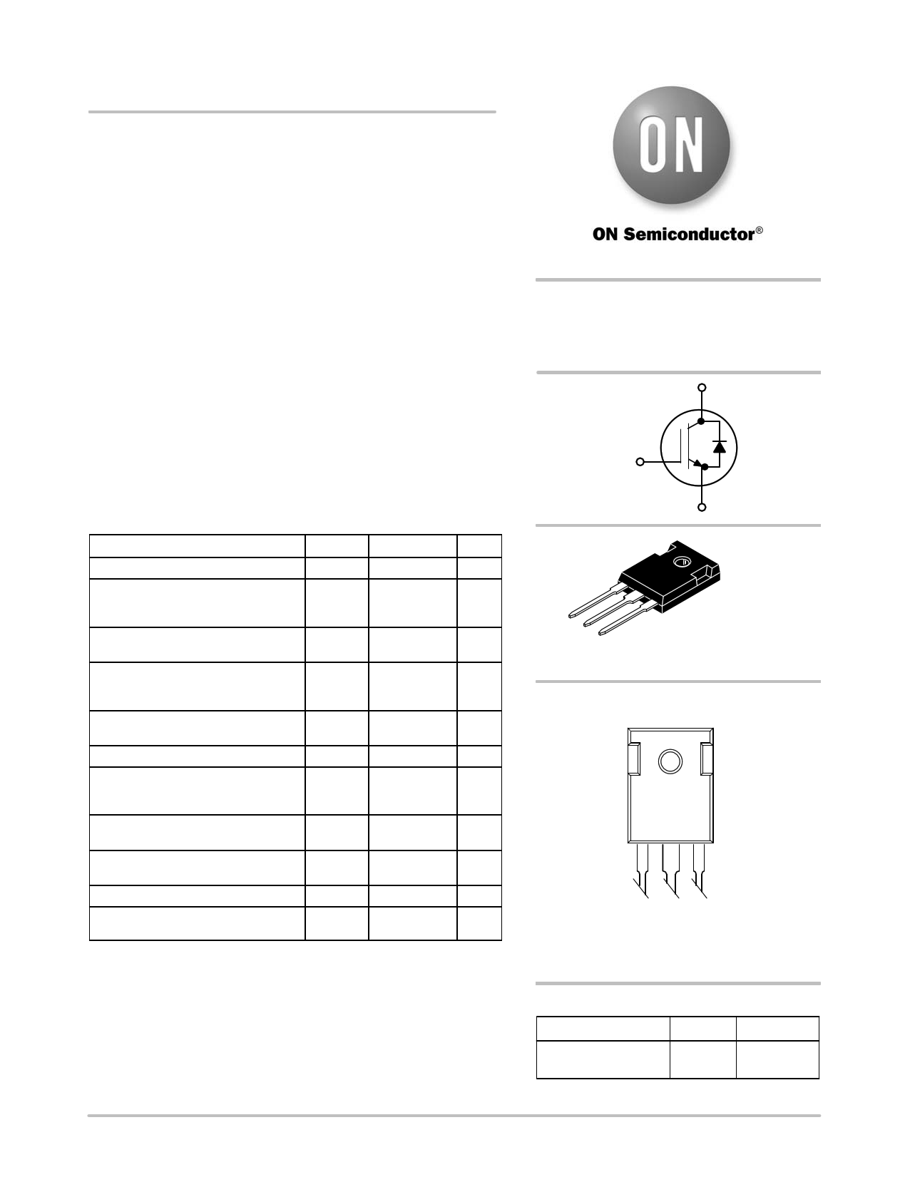
NGTB25N120FLWG
IGBT
This Insulated Gate Bipolar Transistor (IGBT) features a robust and
cost effective Trench construction, and provides superior performance
in demanding switching applications, offering both low on state
voltage and minimal switching loss. The IGBT is well suited for UPS
and solar applications. Incorporated into the device is a soft and fast
co−packaged free wheeling diode with a low forward voltage.
Features
• Low Saturation Voltage using Trench with Field Stop Technology
• Low Switching Loss Reduces System Power Dissipation
• 10 ms Short Circuit Capability
• Low Gate Charge
• Soft, Fast Free Wheeling Diode
• These are Pb−Free Devices
Typical Applications
• Solar Inverter
• UPS Inverter
ABSOLUTE MAXIMUM RATINGS
Rating
Symbol
Value
Unit
Collector−emitter voltage
Collector current
@ TC = 25°C
@ TC = 100°C
Pulsed collector current, Tpulse
limited by TJmax
Diode forward current
@ TC = 25°C
@ TC = 100°C
Diode pulsed current, Tpulse limited
by TJmax
Gate−emitter voltage
Power Dissipation
@ TC = 25°C
@ TC = 100°C
Short Circuit Withstand Time
VGE = 15 V, VCE = 500 V, TJ ≤ 150°C
Operating junction temperature
range
VCES
IC
ICM
IF
IFM
VGE
PD
TSC
TJ
1200
50
25
200
V
A
http://www.DataSheet4U.net/
A
A
50
25
200 A
$20
192
77
10
V
W
ms
−55 to +150 °C
Storage temperature range
Lead temperature for soldering, 1/8”
from case for 5 seconds(note 3)
Tstg
TSLD
−55 to +150
260
°C
°C
Stresses exceeding Maximum Ratings may damage the device. Maximum
Ratings are stress ratings only. Functional operation above the Recommended
Operating Conditions is not implied. Extended exposure to stresses above the
Recommended Operating Conditions may affect device reliability.
http://onsemi.com
25 A, 1200 V
VCEsat = 2.0 V
Eoff = 0.95 mJ
C
G
E
G
CE
TO−247
CASE 340L
STYLE 4
MARKING DIAGRAM
25N120FL
AYWWG
A = Assembly Location
Y = Year
WW = Work Week
G = Pb−Free Package
ORDERING INFORMATION
Device
NGTB25N120FLWG
Package Shipping
TO−247 30 Units / Rail
(Pb−Free)
© Semiconductor Components Industries, LLC, 2012
September, 2012 − Rev. 0
1
Publication Order Number:
NGTB25N120FLW/D
datasheet pdf - http://www.DataSheet4U.net/
1 page 
NGTB25N120FLWG
TYPICAL CHARACTERISTICS
16 2.5
VCE = 600 V
12
VCE = 600 V
VGE = 15 V
2 IC = 25 A
Rg = 10 W
Eon
8 1.5 Eoff
1
4 0.5
0
0 50 100 150 200 250 300 350
QG, GATE CHARGE (nC)
Figure 7. Typical Gate Charge
0
0 20 40 60 80 100 120 140 160
TJ, JUNCTION TEMPERATURE (°C)
Figure 8. Energy Loss vs. Temperature
1000
100 td(on)
tf
td(off)
tr
4
3.5
VCE = 600 V
VGE = 15 V
3
TJ = 150°C
Rg = 10 W
2.5
2
10 VCE = 600 V
VGE = 15 V
IC = 25 A
Rg = 10 W
1.5
1
0.5http://www.DataSheet4U.net/
Eon
Eoff
1
0 20 40 60 80 100 120 140 160
0 8 12 16 20 24 28 32 36 40 44 48 52
TJ, JUNCTION TEMPERATURE (°C)
Figure 9. Switching Time vs. Temperature
IC, COLLECTOR CURRENT (A)
Figure 10. Energy Loss vs. IC
1000
100
tf
td(off)
td(on)
tr
10
VCE = 600 V
VGE = 15 V
TJ = 150°C
1 Rg = 10 W
8 12 16 20 24 28 32 36 40 44 48 52
IC, COLLECTOR CURRENT (A)
Figure 11. Switching Time vs. IC
5.0
4.5
VCE = 600 V
VGE = 15 V
4.0 IC = 25 A
3.5 TJ = 150°C
Eon
3.0
2.5 Eoff
2.0
1.5
1.0
0.5
0
5 15 25 35 45 55 65
Rg, GATE RESISTOR (W)
Figure 12. Energy Loss vs. Rg
75
85
http://onsemi.com
5
datasheet pdf - http://www.DataSheet4U.net/
5 Page | ||
| Páginas | Total 10 Páginas | |
| PDF Descargar | [ Datasheet NGTB25N120FLWG.PDF ] | |
Hoja de datos destacado
| Número de pieza | Descripción | Fabricantes |
| NGTB25N120FLWG | IGBT | ON Semiconductor |
| Número de pieza | Descripción | Fabricantes |
| SLA6805M | High Voltage 3 phase Motor Driver IC. |
Sanken |
| SDC1742 | 12- and 14-Bit Hybrid Synchro / Resolver-to-Digital Converters. |
Analog Devices |
|
DataSheet.es es una pagina web que funciona como un repositorio de manuales o hoja de datos de muchos de los productos más populares, |
| DataSheet.es | 2020 | Privacy Policy | Contacto | Buscar |