|
|
|
PDF MAX6864 Data sheet ( Hoja de datos )
| Número de pieza | MAX6864 | |
| Descripción | (MAX6854 - MAX6869) Nanopower uP Supervisory Circuits | |
| Fabricantes | Maxim Integrated | |
| Logotipo | ||
Hay una vista previa y un enlace de descarga de MAX6864 (archivo pdf) en la parte inferior de esta página. Total 17 Páginas | ||
|
No Preview Available !
19-3139; Rev 2; 9/04
Nanopower µP Supervisory Circuits with
Manual Reset and Watchdog Timer
General Description
The MAX6854/MAX6855/MAX6856/MAX6858/MAX6860–
MAX6869 ultra-low-current (170nA, typ) microprocessor
(µP) supervisory circuits combine voltage monitoring,
watchdog timer, and manual reset input functions in a 5-
pin SOT23 package. These devices assert a reset signal
whenever the monitored voltage drops below the factory-
trimmed reset threshold voltage, manual reset is assert-
ed, or the watchdog timer expires. The reset output
remains asserted for a minimum timeout period after VCC
rises above the reset threshold and manual reset is
deasserted. Factory-trimmed reset threshold voltages
are offered from +1.575V to +4.625V in approximately
100mV increments (see Threshold Suffix Guide). Each
device is offered with six minimum reset timeout options,
ranging from 10ms to 1200ms.
The MAX6854/MAX6855/MAX6856/MAX6858/MAX6860–
MAX6869 are offered in a variety of configurations (see
the Selector Guide). The MAX6854/MAX6855/MAX6856/
MAX6861–MAX6869 provide a manual reset input, MR.
The MAX6864–MAX6869 offer a watchdog timer that
monitors activity at the WDI input to prevent code execu-
tion errors. The MAX6864–MAX6869 offer watchdog
timeout options of 3.3s or 209s (typ). The MAX6861/
MAX6862/MAX6863 feature a pin-selectable reset delay
period of 10ms or 150ms (min). Push-pull active-low,
push-pull active-high, and open-drain active-low reset
outputs are available.
Applications
Portable/Battery-Powered Equipment
PDAs/Cell Phones
MP3 Players/Pagers
Glucose Monitors/Patient Monitors
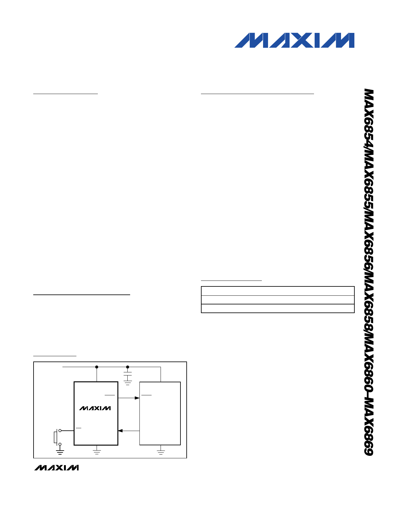
VCC
MANUAL
RESET
Typical Operating Circuit
VCC
RESET
MAX6864
MAX6867
MR WDI
GND
0.1µF
VCC
RESET
µP
I/O
GND
Features
♦ Ultra-Low 170nA (typ) Supply Current
♦ Reset Thresholds from +1.575V to +4.625V in
Approximately 100mV Increments
♦ Six Minimum Reset Timeout Period Options from
10ms to 1200ms
♦ Manual Reset Option
♦ Watchdog Timer Option
♦ Pin-Selectable 10ms/150ms (min) Reset Timeout
Period (MAX6861/MAX6862/MAX6863)
♦ Immune to Short VCC Transients
♦ Guaranteed Reset Valid to VCC = +1.1V
♦ Three Reset Output Options:
Push-Pull RESET
Push-Pull RESET
Open-Drain RESET
♦ No External Components
♦ Small 5-Pin SOT23 Package
♦ Pin Compatible to the TPS3836/TPS3837/TPS3838
(MAX6861/MAX6862/MAX6863)
Ordering Information
PART†
TEMP RANGE PIN-PACKAGE
MAX6854UK_ _D_-T
-40°C to +85°C 5 SOT23-5
MAX6855UK_ _D_-T
-40°C to +85°C 5 SOT23-5
†Insert reset threshold suffix (see Table 2, Threshold Suffix
Guide) after UK. Insert the number corresponding to the
desired reset timeout period (see Table 4, Reset Timeout
Period) after D.
Note: Sample stock is generally held on standard versions
only (see Table 5, Standard Versions Table). Standard versions
have an order increment of 2500 pieces. Nonstandard versions
have an order increment of 10,000 pieces. Contact factory for
availability of nonstandard versions.
Pin Configurations appear at end of data sheet.
Selector Guide appears at end of data sheet.
Ordering Information continued at end of data sheet.
________________________________________________________________ Maxim Integrated Products 1
For pricing, delivery, and ordering information, please contact Maxim/Dallas Direct! at
1-888-629-4642, or visit Maxim’s website at www.maxim-ic.com.
Free Datasheet http://www.datasheet4u.com/
1 page 
Nanopower µP Supervisory Circuits with
Manual Reset and Watchdog Timer
Typical Operating Characteristics (continued)
(VCC = +2.5V, TA = +25°C, unless otherwise noted.)
0.30
0.25
0.20
0.15
0.10
0.05
0
0
OUTPUT LOW VOLTAGE
vs. SINK CURRENT
VCC = 1.8V
VCC = 2.5V
VCC = 3.3V
1000 2000 3000 4000 5000
ISINK (µA)
0.50
0.45
0.40
0.35
0.30
0.25
0.20
0.15
0.10
0.05
0
0
OUTPUT HIGH VOLTAGE
vs. SOURCE CURRENT
VCC = 2.5V
VCC = 1.8V
VCC = 3.3V
200 400 600 800 1000
ISOURCE (µA)
SUPPLY CURRENT vs. WATCHDOG
SWITCHING FREQUENCY
100
VCC = 2.5V
10
1
0.1
10 100 1k 10k 100k 1M 10M
WATCHDOG SWITCHING FREQUENCY (Hz)
VCC TO RESET DELAY
MAX6854 toc11
VCC
1.7V 200mV/div
VTH = 1.575V
1.5V
tRD
RESET
1V/div
0
10µs/div
MANUAL RESET DELAY
MAX6854 toc12
MR
tMRD 1V/div
200ns/div
RESET
1V/div
_______________________________________________________________________________________ 5
Free Datasheet http://www.datasheet4u.com/
5 Page 
Nanopower µP Supervisory Circuits with
Manual Reset and Watchdog Timer
VCC
WDI
OV
VCC
RESET*
OV
tWDI
*RESET IS THE INVERSE OF RESET.
tWD
tRP
Figure 3. Detailed Watchdog Input Timing Relationship
Detailed Description
RESET/RESET Output
A µP’s reset input starts the µP in a known state. The
MAX6854/MAX6855/MAX6856/MAX6858/MAX6860–
MAX6869 µP supervisory circuits assert a reset to prevent
code-execution errors during power-up, power-down, and
brownout conditions. The MAX6854/MAX6855/MAX6856/
MAX6858/MAX6860–MAX6869 reset output is guaranteed
to be valid for VCC down to 1.1V.
Whenever VCC falls below the reset threshold, the reset
output asserts low for RESET and high for RESET.
Once VCC exceeds the reset threshold, an internal
timer keeps the reset output asserted for the specified
reset timeout period, then after this interval the reset
output deasserts (see Figure 2).
Manual Reset Input
Many µP-based products require manual reset capabil-
ity, allowing the operator, a test technician, or external
logic circuitry to initiate a reset. The MAX6854/
MAX6855/MAX6856/MAX6861–MAX6869 feature an
MR input. A logic low on MR asserts a reset. Reset
remains asserted while MR is low and for the timeout
period, tRP, after MR returns high. The devices provide
an internal 10kΩ pullup from MR to VCC. Leave MR
unconnected or connect to VCC if unused. MR can be
driven with CMOS logic levels or with open-drain/col-
lector outputs. Connect a normally open momentary
switch from MR to GND to implement a manual reset
function; external debounce circuitry is not required. If
MR is driven by long cables or the device is used in a
noisy environment, connect a 0.1µF capacitor from MR
to GND to provide additional noise immunity.
Watchdog Input
The MAX6864–MAX6869’s watchdog timer circuitry
monitors the µP’s activity. If the µP does not toggle
(low-to-high or high-to-low) the watchdog input (WDI)
within the watchdog timeout period (tWDI), reset asserts
for the reset timeout period (tRP). The internal timer is
cleared when reset asserts, when manual reset is
asserted, or by a rising or falling edge on WDI. The
watchdog input detects pulses as short as 150ns.
While reset is asserted the watchdog timer does not
count. As soon as reset deasserts, the watchdog timer
resumes counting (Figure 3).
Applications Information
Selecting the Reset Timeout Period
The reset timeout period for the MAX6854/MAX6855/
MAX6856/MAX6858/MAX6860/MAX6864–MAX6869 is
fixed (see Table 4). The MAX6861/MAX6862/MAX6863
feature a reset timeout select input, CT. Connect CT
according to Table 1 to select between the available
10ms and 150ms (min) reset timeout periods. The time-
out period can be changed while a reset timeout period
is in progress, but will not update until the reset timeout
period has expired.
Table 1. MAX6861/MAX6862/MAX6863
Reset Timeout Period Selection
CT CONNECTION
LOW
HIGH
MIN
10
150
TYP
15
225
MAX
25
300
UNITS
ms
______________________________________________________________________________________ 11
Free Datasheet http://www.datasheet4u.com/
11 Page | ||
| Páginas | Total 17 Páginas | |
| PDF Descargar | [ Datasheet MAX6864.PDF ] | |
Hoja de datos destacado
| Número de pieza | Descripción | Fabricantes |
| MAX686 | DAC-Controlled Boost/Inverter LCD Bias Supply with Internal Switch | Maxim Integrated |
| MAX6860 | (MAX6854 - MAX6869) Nanopower uP Supervisory Circuits | Maxim Integrated |
| MAX6861 | (MAX6854 - MAX6869) Nanopower uP Supervisory Circuits | Maxim Integrated |
| MAX6862 | (MAX6854 - MAX6869) Nanopower uP Supervisory Circuits | Maxim Integrated |
| Número de pieza | Descripción | Fabricantes |
| SLA6805M | High Voltage 3 phase Motor Driver IC. |
Sanken |
| SDC1742 | 12- and 14-Bit Hybrid Synchro / Resolver-to-Digital Converters. |
Analog Devices |
|
DataSheet.es es una pagina web que funciona como un repositorio de manuales o hoja de datos de muchos de los productos más populares, |
| DataSheet.es | 2020 | Privacy Policy | Contacto | Buscar |