|
|
|
PDF 10XS3535 Data sheet ( Hoja de datos )
| Número de pieza | 10XS3535 | |
| Descripción | Smart Front Corner Light Switch | |
| Fabricantes | Freescale Semiconductor | |
| Logotipo | ||
Hay una vista previa y un enlace de descarga de 10XS3535 (archivo pdf) en la parte inferior de esta página. Total 30 Páginas | ||
|
No Preview Available !
Freescale Semiconductor
Technical Data
Document Number: MC10XS3535
Rev. 6.0, 6/2012
Smart Front Corner Light Switch
(Triple 10 mOhm and Dual
35 mOhm)
10XS3535
The 10XS3535 is designed for low voltage automotive and industrial
lighting applications. Its five low RDS(ON) MOSFETs (three 10 mΩ, two
35 mΩ) can control the high sides of five separate resistive loads
(bulbs, Xenon-HID modules and LEDs).
Programming, control and diagnostics are accomplished using a
16-bit SPI interface (3.3 V or 5.0 V). Each output has its own pulse-
width modulation (PWM) control via the SPI. The 10XS3535 has highly
sophisticated failure mode handling to provide high availability of the
outputs. Its multiphase control and output edge shaping improves
electromagnetic compatibility (EMC) behavior.
The 10XS3535 is packaged in a power-enhanced 12 x 12 mm
nonleaded PQFN package with exposed tabs.
Features
• Triple 10 mΩ and dual 35 mΩ high side switches
• 16-bit SPI communication interface with daisy chain capability
• Current sense output with SPI-programmable multiplex switch
and board temperature feedback
• Digital diagnosis feature
• PWM module with multiphase feature including prescaler
• LEDs control including accurate current sensing and low duty-
cycle capability
• Fully protected switches
• Over-current shutdown detection
• Power net and reverse polarity protection
• Low-power mode
• Fail mode functions including autorestart feature
• External smart power switch control including current recopy
HIGH SIDE SWITCH
Bottom View
FK SUFFIX
98ART10511D
24-PIN PQFN
PB FREE
ORDERING INFORMATION
Device
(For Tape and Reel,
add R2 Suffix)
Temperature
Range (TA)
Package
MC10XS3535HFK
-40 to 125 °C
24 PQFN
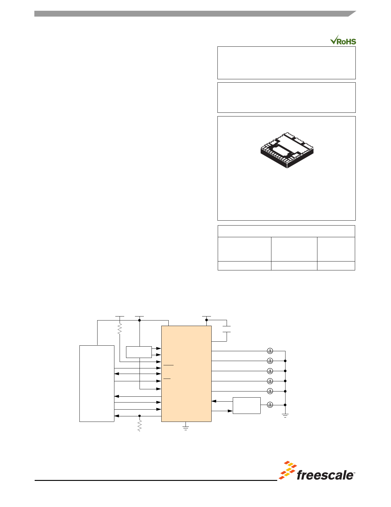
12V 5.0V
Watchdog
MCU
12V
10XS3535
VCC
VBAT
CP
LIMP
FLASHER
IGN
OUT1
OUT2
RST
CLOCK
CS
OUT3
OUT4
FOG
S0
SI
OUT5
FETIN
SCLK
FETOUT
CSNS GND
Smart
Switch
Figure 1. 10XS3535 Simplified Application Diagram
Freescale Semiconductor, Inc. reserves the right to change the detail specifications,
as may be required, to permit improvements in the design of its products.
© Freescale Semiconductor, Inc., 2010-2012. All rights reserved.
Free Datasheet http://www.datasheet4u.com/
1 page 
ELECTRICAL CHARACTERISTICS
MAXIMUM RATINGS
ELECTRICAL CHARACTERISTICS
MAXIMUM RATINGS
Table 2. Maximum Ratings
All voltages are with respect to ground unless otherwise noted. Exceeding these ratings may cause a malfunction or
permanent damage to the device.
Ratings
Symbol
Value
Unit
ELECTRICAL RATINGS
Over-voltage Test Range (all OUT[1:5] ON with nominal DC current)
Maximum Operating Voltage
Load Dump (400 ms) @ 25 °C
VBAT
28
40
V
Reverse Polarity Voltage Range (all OUT[1:5] ON with nominal DC current)
2.0 Min @ 25 °C
VBAT
- 18
V
VCC Supply Voltage
OUT[1:5] Voltage
Positive
Negative (ground disconnected)
VCC
VOUT
-0.3 to 5.5
40
-16
V
V
Digital Current in Clamping Mode (SI, SCLK, CS, RST, IGN, FLASHER, LIMP
and FOG)
IIN
±1.0 mA
FETIN Input Current
IFETIN
+10
-1.0
mA
SO, FETOUT, CLOCK and CSNS Outputs Voltage
Outputs clamp energy using single pulse method (L = 2 mH; R = 0 Ω;
VBAT = 14 V @150°C initial)
OUT[1,5]
OUT[2:4]
ESD Voltage(2)
Human Body Model (HBM)
Human Body Model (HBM) OUT [1:5], VPWR, and GND
Charge Device Model (CDM)
Corner Pins (1, 13, 19, 21)
All Other Pins (2-12, 14-18, 20, 22-24)
VSO
E1,5
E2,3,4
VESD
-0.3 to VCC+0.3
30
100
±2000
±8000
±750
±500
V
mJ
V
Notes
2. ESD testing is performed in accordance with the Human Body Model (HBM) (CZAP = 100 pF, RZAP = 1500 Ω) and the Charge Device
Model.
Analog Integrated Circuit Device Data
Freescale Semiconductor
10XS3535
5
Free Datasheet http://www.datasheet4u.com/
5 Page 
ELECTRICAL CHARACTERISTICS
STATIC ELECTRICAL CHARACTERISTICS
Table 3. Static Electrical Characteristics (continued)
Characteristics noted under conditions 3.0 V ≤ VCC ≤ 5.5 V, 7.0 V ≤ VBAT ≤ 2 0V, -40 °C ≤ TA ≤ 125 °C, GND = 0 V, unless
otherwise noted. Typical values noted reflect the approximate parameter means at TA = 25 °C under nominal conditions, unless
otherwise noted.
Characteristic
Symbol
Min Typ Max Unit
PARKING LIGHT OUT1 (CONTINUED)
High Over-current Shutdown Threshold 2
Low Over-current Shutdown Threshold
Open Load-current Threshold in ON State(17)
Open Load-current Threshold in ON State with LED(18)
VOUT = VBAT - 0.8 V
Current Sense Full-Scale Range(19)
Current Sense Full-Scale Range(19) depending on LED Control = 1
Severe short-circuit impedance range(20)
IOCHI2
IOCLO
IOL
IOLLED
ICS FSR
ICS FSR_LED
RSC1(OUT1)
12.3
5.7
0.05
4.0
–
–
350
15.4
7.2
0.2
10.0
5.7
1.6
–
18.5
8.9
0.5
20.0
–
–
–
A
A
A
mA
A
A
mΩ
LOW BEAM OUT2
Output Drain-to-Source ON Resistance (IOUT = 5.5 A, TA = 25 °C)
VBAT = 13.5 V
VBAT = 7.0 V
RDS(ON)
–
–
mΩ
– 10
– 15
Output Drain-to-Source ON Resistance (IOUT = 5.5 A, VBAT = 13.5 V,
TA = 150 °C)(20)
Reverse Source-to-Drain ON Resistance (IOUT = -5.5 A, TA = 25 °C)(21)
VBAT = -12 V
RDS(ON)
RSD(ON)
–
–
mΩ
– 17.0
mΩ
– 20
High Over-current Shutdown Threshold 1
VBAT = 16 V, TA = -40 °C
VBAT = 16 V, TA = 25 °C
VBAT = 16 V, TA = 125 °C
IOCHI1
63.2 79.0 94.8 A
67.2 80.0 92.8
66.3 79.0 91.7
62.5 74.5 86.5
High Over-current Shutdown Threshold 2
Low Over-current Shutdown Threshold
Optional Xenon Bulb
Optional H7 Bulb
Open Load Current Threshold in ON State(22)
Open Load Current Threshold in ON State with LED(23)
VOL = VBAT - 0.8 V
Current Sense Full-scale Range(24)
Optional Xenon Bulb
Optional H7 Bulb
IOCHI2
IOCLO
IOL
IOLLED
ICS FSR
26.2 32.8 39.4 A
A
17.6 22.0 26.4
12.1 15.2 18.3
0.1 0.4 1.0 A
mA
4.0 10.0 20.0
A
– 21.9 –
– 12.5 –
Severe short-circuit impedance range(20)
RSC1(OUT2)
100
–
– mΩ
Notes
17. OLLED1, bit D0 in SI data is set to [0].
18. OLLED1, bit D0 in SI data is set to [1].
19. For typical value of ICS FSR, ICSNS = 5.0 mA. If the range is exceeded, no current clamp and the precision is no more guaranteed.
20. Parameter guaranteed by design; however, it is not production tested.
21. Source-to-Drain ON Resistance (Reverse Drain-to-Source ON Resistance) with negative polarity VBAT.
22. OLLED2, bit D1 in SI data is set to [0].
23. OLLED2, bit D1 in SI data is set to [1].
24. For typical value of ICS FSR, ICSNS = 5.0 mA. If the range is exceeded, no current clamp and the precision is no more guaranteed
Analog Integrated Circuit Device Data
Freescale Semiconductor
10XS3535
11
Free Datasheet http://www.datasheet4u.com/
11 Page | ||
| Páginas | Total 30 Páginas | |
| PDF Descargar | [ Datasheet 10XS3535.PDF ] | |
Hoja de datos destacado
| Número de pieza | Descripción | Fabricantes |
| 10XS3535 | Smart Front Corner Light Switch | Freescale Semiconductor |
| Número de pieza | Descripción | Fabricantes |
| SLA6805M | High Voltage 3 phase Motor Driver IC. |
Sanken |
| SDC1742 | 12- and 14-Bit Hybrid Synchro / Resolver-to-Digital Converters. |
Analog Devices |
|
DataSheet.es es una pagina web que funciona como un repositorio de manuales o hoja de datos de muchos de los productos más populares, |
| DataSheet.es | 2020 | Privacy Policy | Contacto | Buscar |