|
|
|
PDF MBU103 Data sheet ( Hoja de datos )
| Número de pieza | MBU103 | |
| Descripción | (MBU100 Series) Single Output DC/DC Converter | |
| Fabricantes | Minmax Technology | |
| Logotipo | ||
Hay una vista previa y un enlace de descarga de MBU103 (archivo pdf) en la parte inferior de esta página. Total 6 Páginas | ||
|
No Preview Available !
MBU100 Series
1W, Ultra Miniature SIP, Single Output DC/DC Converter
Key Features
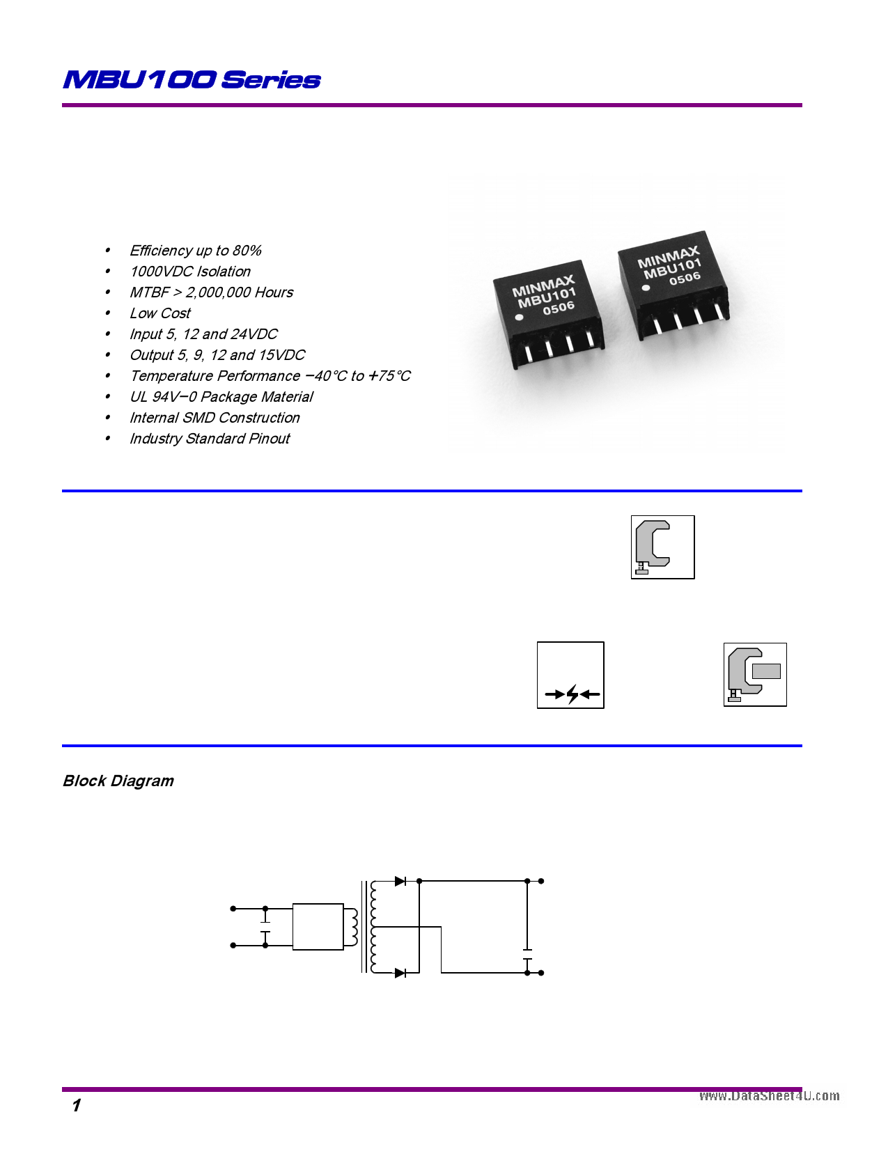
y Efficiency up to 80%
y 1000VDC Isolation
y MTBF > 2,000,000 Hours
y Low Cost
y Input 5, 12 and 24VDC
y Output 5, 9, 12 and 15VDC
y Temperature Performance -40] to +75]
y UL 94V-0 Package Material
y Internal SMD Construction
y Industry Standard Pinout
Taking up as little as 0.18 square inches of board space,
Minmax's MBU100 1W DC/DC's are specially designed to
provide power distribution applications where space is critical
in anwww.DataSheet4U.com ultra-miniature SIP package.
The series consists of 12 models with input voltages of
5V, 12V and 24VDC which offers standard single output
voltages of 5V, 9V, 12V, 15VDC.
The MBU100 series is an excellent selection for a variety
of applications including distributed power systems, mixed
analog/digital subsystems, portable test equipments, local
power networks and battery backed systems.
Block Diagram
$
Low Cost
1000
VDC
I/O Isolation
Low Profile
+Vin
-Vin
Bipolar
Push-Pull
Inverter
+Vo
-Vo
1
MINMAX
REV:0 2005/04
1 page 
MBU100 Series
Test Configurations
Input Reflected-Ripple Current Test Setup
Input reflected-ripple current is measured with a inductor
Lin (4.7uH) and Cin (220uF, ESR < 1.0[ at 100 KHz) to
simulate source impedance.
Capacitor Cin, offsets possible battery impedance.
Current ripple is measured at the input terminals of the
module, measurement bandwidth is 0-500 KHz.
To Oscilloscope
+Vin +Out
+
Battery
+ Lin
Cin
Current
Probe
DC / DC
Converter
-Vin -Out
Load
+
DC Power
Source
-
+Vin
+ DC / DC
Converter
Cin
-Vin
+Out
-Out
Load
Output Ripple Reduction
A good quality low ESR capacitor placed as close as
practicable across the load will give the best ripple and noise
performance.
To reduce output ripple, it is recommended to use 1uF
capacitors at the output.
Peak-to-Peak Output Noise Measurement Test
Use a Cout 0.33uF ceramic capacitor.
Scope measurement should be made by using a BNC
socket, measurement bandwidth is 0-20 MHz. Position the
load between 50 mm and 75 mm from the DC/DC Converter.
+
DC Power
Source
-
+Vin
+Out
Single Output
DC / DC
Converter
-Vin -Out
Cout
Load
+Vin
+Out
Single Output
DC / DC
Converter
-Vin -Out
Copper Strip
Cout
Scope
Resistive
Load
Design & Feature Considerations
Maximum Capacitive Load
Thermal Considerations
Many conditions affect the thermal performance of the
power module, such as orientation, airflow over the module
and board spacing. To avoid exceeding the maximum
temperature rating of the components inside the power
module, the case temperature must be kept below 90°C.
The derating curves are determined from measurements
obtained in an experimental apparatus.
The MBU100 series has limitation of maximum connected
capacitance at the output.
The power module may be operated in current limiting
mode during start-up, affecting the ramp-up and the startup
time.
For optimum performance we recommend 33uF maximum
capacitive load for devices.
The maximum capacitance can be found in the data sheet.
Position of air velocity
probe and thermocouple
15mm / 0.6in
50mm / 2in
Air Flow
DUT
Input Source Impedance
The power module should be connected to a low
ac-impedance input source. Highly inductive source
impedances can affect the stability of the power module.
In applications where power is supplied over long lines and
output loading is high, it may be necessary to use a capacitor
at the input to ensure startup.
Capacitor mounted close to the power module helps
ensure stability of the unit, it is recommended to use a good
quality low Equivalent Series Resistance (ESR < 1.0[ at 100
KHz) capacitor of a 1.5uF for the 5V input devices, a 1.0uF for
the 12V input devices and a 0.47uF for the 24V devices.
5
MINMAX
REV:0 2005/04
5 Page | ||
| Páginas | Total 6 Páginas | |
| PDF Descargar | [ Datasheet MBU103.PDF ] | |
Hoja de datos destacado
| Número de pieza | Descripción | Fabricantes |
| MBU100 | MBU100 SERIES 1WATT ULTRA MINIATURE HIGH SIP DC/DC CONVERTERS | Total Power International |
| MBU100 | (MBU100 Series) Single Output DC/DC Converter | Minmax Technology |
| MBU101 | (MBU100 Series) Single Output DC/DC Converter | Minmax Technology |
| MBU102 | (MBU100 Series) Single Output DC/DC Converter | Minmax Technology |
| Número de pieza | Descripción | Fabricantes |
| SLA6805M | High Voltage 3 phase Motor Driver IC. |
Sanken |
| SDC1742 | 12- and 14-Bit Hybrid Synchro / Resolver-to-Digital Converters. |
Analog Devices |
|
DataSheet.es es una pagina web que funciona como un repositorio de manuales o hoja de datos de muchos de los productos más populares, |
| DataSheet.es | 2020 | Privacy Policy | Contacto | Buscar |