|
|
|
PDF SP12352R7YLx-xxx Data sheet ( Hoja de datos )
| Número de pieza | SP12352R7YLx-xxx | |
| Descripción | Shielded SMD Power Inductor | |
| Fabricantes | ABC | |
| Logotipo | ||
Hay una vista previa y un enlace de descarga de SP12352R7YLx-xxx (archivo pdf) en la parte inferior de esta página. Total 5 Páginas | ||
|
No Preview Available !
SPECIFICATION FOR APPROVAL
REF. :
PROD.
NAME
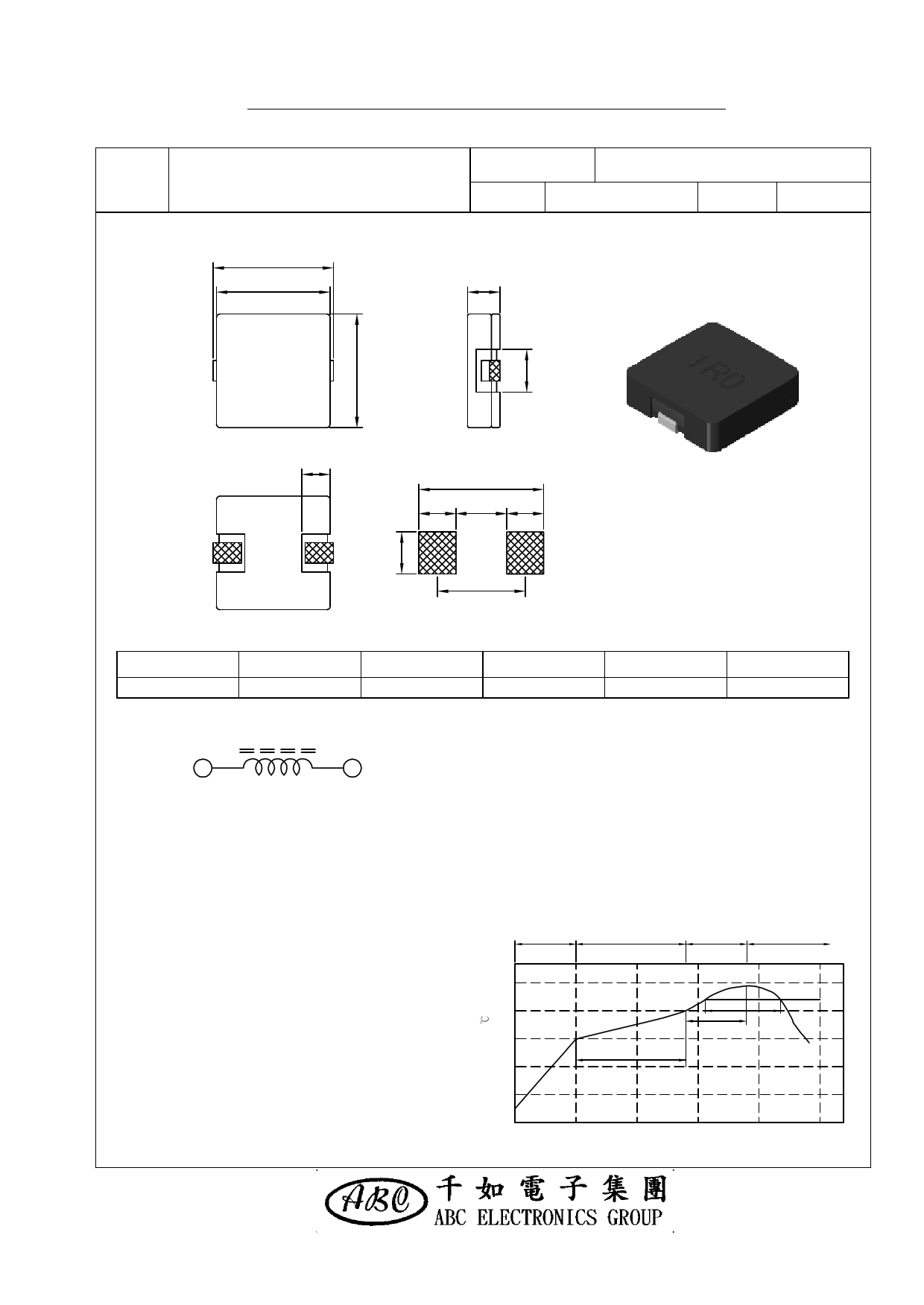
Shielded SMD Power Inductor
Ⅰ﹒Configuration and dimensions:
B'
B
ABC'S DWG NO.
SP1235□□□□L□-□□□
REV.
20130503-A
PAGE
1
C
E
13.6
4.0 5.6 4.0
A
12.70±0.30
B
12.70±0.30
Ⅱ﹒Schematic diagram:
9.6
( PCB Pattern )
B'
13.00±0.30
C
3.50±0.30
D
4.20 typ.
Unit:m/m
E
3.30 typ.
12
Ⅲ﹒Description:
a﹒Ferrite ER core construction.
b﹒Magnetically shielded.
c﹒Enamelled copper wire:F class
d﹒Product weight: 3.10 g(ref.)
e﹒Moisture sensitivity Level 1
f﹒Products comply with RoHS' requirements
g﹒Halogen free available
Ⅳ﹒General specification:
a﹒Storage temp.:-55℃ ~ +125℃
b﹒Operating temp .:-55℃ ~ +125℃
( Temp. rise included )
c﹒Resistance to solder heat:245℃. 10 secs.
AR-001C
Temperature
Rising Area
+4.0℃ / sec max.
250
200
150
100
Peak Temp:245℃ max.
Max. Peak Temp - 5℃:30sec max.
Max time above 217℃ :60sec~150sec max.
Preheat Area
150 ~ 200℃ / 60 ~ 120sec
Reflow Area Forced Cooling Area
+3.0℃ / sec max. -(1.0 ~ 5.0)℃ / sec max.
Peak Temperature:
245℃
60sec~150sec
60sec max.
217℃
60sec~120sec
50
0 50 100 150 200 250
Time ( seconds )
Free Datasheet http://www.datasheet4u.com/
1 page 
SPECIFICATION FOR APPROVAL
REF. :
PROD.
NAME
Shielded SMD Power Inductor
Ⅶ﹒Reliability test:
ABC'S DWG NO.
SP1235□□□□L□-□□□
REV.
20130503-A
PAGE
5
Item Reference documents
Test Condition
Test Specification
1.High Temperature
Exposure
MIL-STD-202 Method 108 1.Temperature: 125℃
2.Time:96 hours.
2.Temperature Cycling JESD22 Method JA-104
1.Temperature: -55℃ ~ 125℃
2.Number of cycle:96 cycle
3.Dwell time:30 minutes
1.Temperature: 85±5 ℃
3.Biased Humidity Test MIL-STD-202 Method 103 2.Time:96 Hours
3.Humidity: 85±5% RH.
4.Operational Life
MIL-PRF-27
1.Temperature: 125℃
2.Time:96 hours.
3.Apply rated current.
5.Exeternal Visual
Inspect product
MIL-STD-883 Method 2009 constructions, marking and
workmanship.
6.Physical Dimensions JESD22 Method JB-100
Verify physical dimensions to
the applicable product detail
specification.
1.No mechanical and electrical
damage.
2.Inductance shall not change
more than ±25%.
1.No mechanical and electrical
damage.
2.Inductance shall not change
more than ±25%.
1.No mechanical and electrical
damage.
2.Inductance shall not change
more than ±25%.
1.No mechanical and electrical
damage.
2.Inductance shall not change
more than ±25%.
1.No pollution on the surface of
products.
2.Clear marking.
3.No crack.
Per product specification
standard
7.Resistance to solvents MIL-STD-202 Method 215
8.Vibration Test
MIL-STD-202 Method 204
9.Resistance To
Soldering Heat Test
MIL-STD-202 Method 210
10.Rated current
MIL-STD-202 Method 330
11.Temperature rise MIL-PRF-27
12.Over load
MIL-PRF-27
13.Solderability Test J-STD-002
14.Electrical
Characteriazation
15.Withstanding
Voltage Test
User Spec.
MIL-STD-202 Method 201
16.Drop
JESD22-B111
17.Terminal Strength
Test
JIS-C-6429
Immerse into solvent for 3±0.5 minutes &
brush 10 times for therr cycles.
1.No body change in apperarance.
2.No marking blurred.
3.Inductance shall not change
more than ±25%.
1.Frequency and Amplitued :
10-2000-10 Hz, 1.5 mm.
2.Direction:X, Y, Z
3.Test duration:2 hours for each direction,
6 hours in total.
1.No mechanical and electrical
damage.
2.Inductance shall not change
more than ±25%.
1.Highest temperature:245±5℃
2.Time(temp.≧ 217℃):60~150 Second.
3.IR reflow times:3 times.
1.No mechanical and electrical
damage.
2.Inductance shall not change
more than ±25%.
Apply rated current for 5 second.
1.No mechanical and electrical
damage.
2.Inductance shall not change
more than ±25%.
Apply rated current for 10 minutes.
1.No mechanical and electrical
damage.
2.Inductance shall not change
more than ±25%.
1.No mechanical and electrical
Apply twice as rated current for 5 minutes. damage.
(It's not application to some special design) 2.Inductance shall not change
more than ±25%.
1.Baking in pre-testing:
155±5℃ / 16Hours±30 min.
2.Peak temperature:240±5℃
3.Time(temp.≧217℃):60~150 second.
4.IR reflow times:1 times.
The terminal shall be at least 95%
covered with fresh solder.
1.Operating temperature: -55℃~125℃
2.Room temperature:25℃.
1.No mechanical and electrical
damage.
2.Inductance shall not change
more than ±25%.
1.DV:500V
2.Time:1minutes
1.During the test no breakdown.
2.The characteristic is normal after test.
Packaged & Drop down from 1m.In 1 angle
1ridges & 2 surfaces orientation.
1.No case deformation or change in
appearance.
2.Inductance shall not change
more than ±25%.
1.Apply push force to samples
mounted on PCB.
2.Force of 1.8 kg for 60±1 seconds.
After test, inductors shall be no
mechanical damage.
AR-001A
Free Datasheet http://www.datasheet4u.com/
5 Page | ||
| Páginas | Total 5 Páginas | |
| PDF Descargar | [ Datasheet SP12352R7YLx-xxx.PDF ] | |
Hoja de datos destacado
| Número de pieza | Descripción | Fabricantes |
| SP12352R7YLx-xxx | Shielded SMD Power Inductor | ABC |
| Número de pieza | Descripción | Fabricantes |
| SLA6805M | High Voltage 3 phase Motor Driver IC. |
Sanken |
| SDC1742 | 12- and 14-Bit Hybrid Synchro / Resolver-to-Digital Converters. |
Analog Devices |
|
DataSheet.es es una pagina web que funciona como un repositorio de manuales o hoja de datos de muchos de los productos más populares, |
| DataSheet.es | 2020 | Privacy Policy | Contacto | Buscar |