|
|
|
PDF BD9329AEFJ Data sheet ( Hoja de datos )
| Número de pieza | BD9329AEFJ | |
| Descripción | Synchronous Buck Converter | |
| Fabricantes | ROHM Semiconductor | |
| Logotipo | ||
Hay una vista previa y un enlace de descarga de BD9329AEFJ (archivo pdf) en la parte inferior de esta página. Total 22 Páginas | ||
|
No Preview Available !
Datasheet
4.2V to 18V, 3A 1ch
Synchronous Buck Converter with
Integrated FET
BD9329AEFJ
General Description
The BD9329AEFJ is a synchronous step-down
switching regulator with built-in two low-resistance
N-Channel MOSFETs. This IC can supply continuous
output current of 3A over a wide input range, and
provides not only fast transient response, but also easy
phase compensation because of current mode control.
Features
Uses Low ESR Output Ceramic Capacitors
Low Standby Current
380 kHz Fixed Operating Frequency
Feedback Voltage
0.9V ± 1.5%(Ta=25°C)
0.9V ± 2.0%(Ta=-25°C to +85°C)
Under Voltage Protection
Thermal Shutdown
Over Current Protection
Key Specifications
Input Voltage Range:
Output Voltage Range:
Output Current:
Switching Frequency
Hi-Side FET ON-Resistance:
Lo-Side FET ON-Resistance:
Standby Current:
Operating Temperature Range:
4.2V to 18V
0.9V to (VIN x 0.7)V
3.0A (Max)
380kHz(Typ)
0.15Ω(Typ)
0.13Ω(Typ)
15μA (Typ)
-40°C to +85°C
Package
W(Typ) D(Typ) H(Max)
Applications
Distributed Power Systems
Pre-Regulator for Linear Regulators
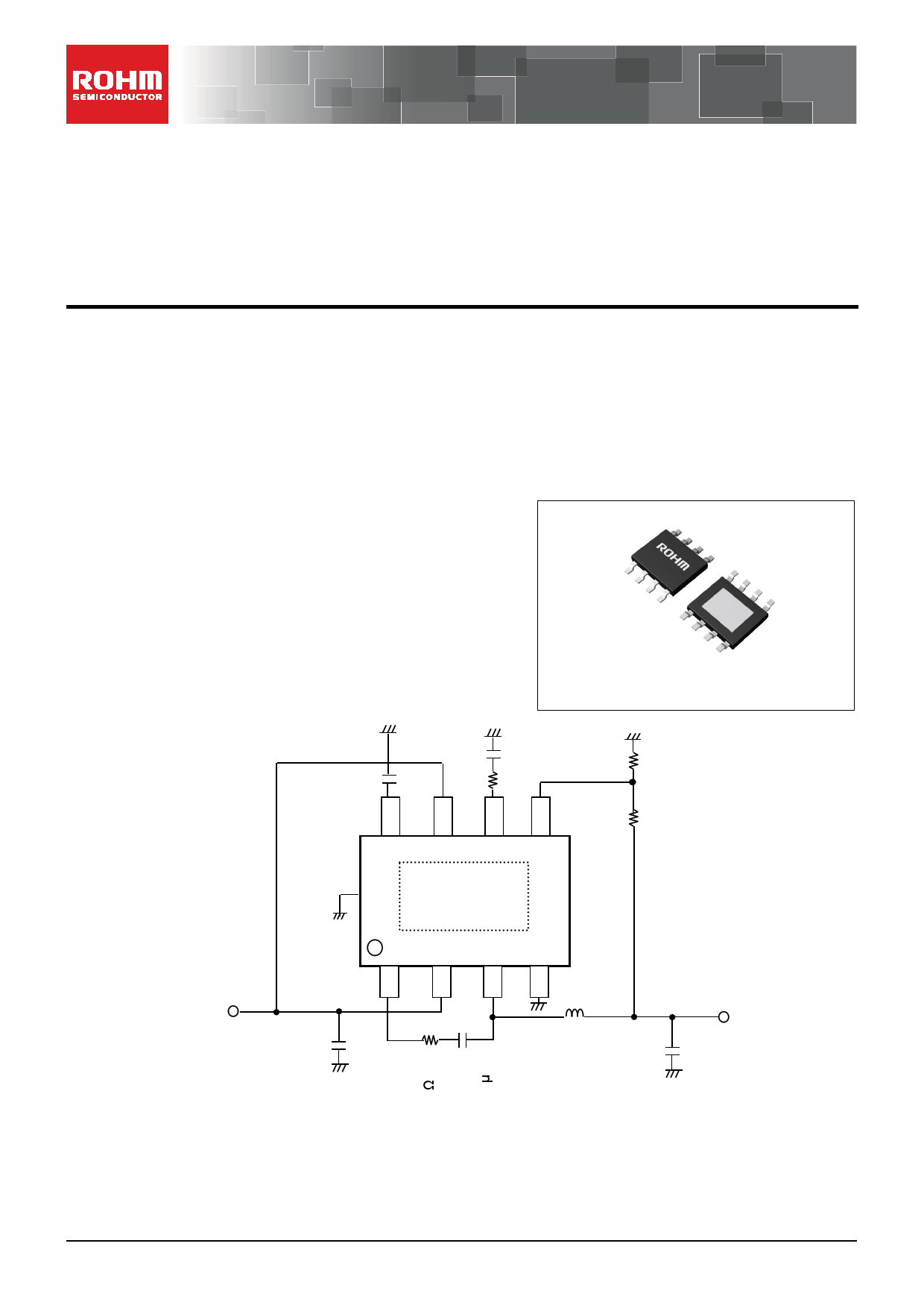
Typical Application Circuit
C_SS
0.1μF
C_PC
3300pF
R_PC
7.5kΩ
HTSOP-J8
4.90mm x 6.00mm x 1.00mm
R_DW
10kΩ
R_UP
27kΩ
Thermal Pad
(to be shorted to GND)
VIN = 12V
C_VC1
10μF
L
10µH
VOUT = 3.3V
C_CO1
20μF
R_BS protects from VIN-BST short destruction.
Figure 1. Typical Application Circuit
〇Product structure : Silicon monolithic integrated circuit
www.rohm.com
© 2012 ROHM Co., Ltd. All rights reserved.
TSZ22111・14・001
〇This product has no designed protection against radioactive rays
1/19
TSZ02201-0323AAJ00010-1-2
16.Feb.2015 Rev.003
1 page 
BD9329AEFJ
Typical Performance Curves - continued
Temp [°C]
Figure 8. Hi-Side, Low-Side FET
ON-Resistance vs Temperature
390
385
380
375
370
365
360
-40 -20 0 20 40 60 80
TTEemMpP[°(C°]C)
Figure 9. Operating Frequency vs
Temperature
IO [mA]
Figure 10. STEP-Down Efficiency vs IO
(VIN= 12V VOUT= 3.3V L=10µH)
CSS [µF]
Figure 11. Soft Start Time vs CSS
www.rohm.com
© 2012 ROHM Co., Ltd. All rights reserved.
TSZ22111・15・001
5/19
TSZ02201-0323AAJ00010-1-2
16.Feb.2015 Rev.003
5 Page 
BD9329AEFJ
(a) Choosing phase compensation resistor RCMP
The compensation resistor RCMP can be calculated using the following formula:
RCMP
=
2π
× VOUT × fCRS × COUT
VFB × GMP × GMA
[Ω]
Where:
VOUT is the Output Voltage
fCRS is the Cross Over Frequency
COUT is the Output Capacitor
VFB is the Internal Feedback Voltage (0.9V(TYP))
GMP is the Current Sense Gain (7.8A/V(TYP))
GMA is the Error Amplifier Transconductance (300µA/V(TYP))
Setting VOUT= 3.3V, fCRS= 38kHz, COUT= 20µF;
RCMP
=
2π × 3.3 × 38k × 20µ
0.9 × 7.8 × 300µ
= 7482.5 ≈
7.5k
[Ω]
(b) Choosing phase compensation capacitor CCMP
For the stability of the DC/DC converter, cancellation of the phase delay that is drawn from the output capacitor COUT
and resistive load ROUT is possible by inserting the phase advance.
The phase advance can be added by the zero on compensation resistor RCMP and capacitor CCMP.
Making fz= fCRS / 6 gives a first-order estimate of CCMP.
Compensation Capacitor
CCMP
=
2π
×
1
RCMP
×
fZ
[F ]
Setting fZ= fCRS/6 = 6.3kHz;
Compensation Capacitor
C CMP
=
2π
1
× 7.5k
× 6.3k
= 3.368 × 10⁻⁹
≅ 3.3 × 10⁻⁹
[F]
However, the best values for zero and fCRS differ between applications. Decide the values accordingly after
calculation using the formula above and confirmation on the actual application.
(c) The condition of the loop compensation stability
The stability of DC/DC converter is important. To secure operation stability, check if the loop compensation has
enough phase-margin. For the condition of loop compensation stability, the phase-delay must be less than 150
degrees at 0 dB Gain.
Feed-forward capacitor CRUP boosts phase margin over a limited frequency range and is sometimes used to improve
loop response. CRUP will be more effective if RUP >> RUP||RDW
VOUT
RUP
RDW
CRUP
FB
-
+
0.9V
COMP
RCMP
CCMP
Figure 21
(3) Design of Feedback Resistance constant
Set the feedback resistance as shown below.
A
Gain [dB]
0
PPHhaAsSeE 0
-90
-180
(a)
GBW(b)
-90°
FfCCRRSS
PPHhAaSsEe MMAaRrgGinIN
-180°
Figure 22
F
F
VOUT
R1
R2
0.9V
+
-ERR
FB
Figure 23
VOUT
=
R1 + R2 × 0.9
R2
[V ]
www.rohm.com
© 2012 ROHM Co., Ltd. All rights reserved.
TSZ22111・15・001
11/19
TSZ02201-0323AAJ00010-1-2
16.Feb.2015 Rev.003
11 Page | ||
| Páginas | Total 22 Páginas | |
| PDF Descargar | [ Datasheet BD9329AEFJ.PDF ] | |
Hoja de datos destacado
| Número de pieza | Descripción | Fabricantes |
| BD9329AEFJ | Synchronous Buck Converter | ROHM Semiconductor |
| Número de pieza | Descripción | Fabricantes |
| SLA6805M | High Voltage 3 phase Motor Driver IC. |
Sanken |
| SDC1742 | 12- and 14-Bit Hybrid Synchro / Resolver-to-Digital Converters. |
Analog Devices |
|
DataSheet.es es una pagina web que funciona como un repositorio de manuales o hoja de datos de muchos de los productos más populares, |
| DataSheet.es | 2020 | Privacy Policy | Contacto | Buscar |