|
|
|
PDF TISP61089B Data sheet ( Hoja de datos )
| Número de pieza | TISP61089B | |
| Descripción | High Voltage Ringing SLIC Protector | |
| Fabricantes | Bourns | |
| Logotipo | ||
Hay una vista previa y un enlace de descarga de TISP61089B (archivo pdf) en la parte inferior de esta página. Total 20 Páginas | ||
|
No Preview Available !
TISP61089B
DUAL FORWARD-CONDUCTING P-GATE THYRISTORS
PROGRAMMABLE OVERVOLTAGE PROTECTORS
TISP61089B High Voltage Ringing SLIC Protector
Dual Voltage-Programmable Protectors
- Supports Battery Voltages Down to -155 V
- Low 5 mA max. Gate Triggering Current
- High 150 mA min. Holding Current
Rated for LSSGR ‘1089 Conditions
Impulse
Waveshape
2/10
10/360
10/1000
‘1089 Test
Section Test #
4.5.7
4.5.8
4
1
4.5.7
2, 5
4.5.7
1,3
I TSP
A
120
30
30
60 Hz Power
Fault Times
0.5
1
2
5
30
900
‘1089 Test
Section Test #
4.5.12
9
4.5.12 3, 4, 8
4.5.12
7
4.5.12
4.5.13
5
2, 3
4.5.12
6
4.5.12
4.5.13
4.5.15/16
1, 2
1, 4, 5
I TSM
A
6.5
4.6
3.4
2.3
1.3
0.73
2/10 Overshoot Voltage Specified
Element
Diode
SCR
ITM = 100 A, di/dt = 80 A/µs
V
10
12
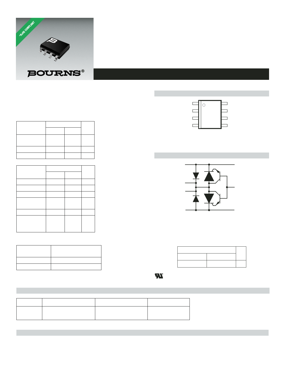
D Package (Top View)
(Tip) K1
(Gate) G
1
2
8 K1 (Tip)
7 A (Ground)
NC 3
6 A (Ground)
(Ring) K2
4
5 K2 (Ring)
MD6XANB
NC - No internal connection
Terminal typical application names shown in
parenthesis
Device Symbol
K1
K1
A
G
A
K2 K2
Te rminals K1, K2 and A correspond to the alternative
line designators of T, R and G or A, B and C. The
negative protection voltage is controlled by the
voltage, VGG, applied to the G terminal.
SD6XAEB
Rated for ITU-T K.20, K.21 and K.45
Waveshape
Voltage
10/700
Current
5/310
ITSP
A
40
............................................ UL Recognized Components
How To Order
Device
TISP61089B
Package
D (8-pin Small-Outline)
Carrier
Embossed Tape Reeled
Order As
TISP61089BDR-S
Description
The TISP61089B is a dual forward-conducting buffered p-gate thyristor (SCR) overvoltage protector. It is designed to protect monolithic SLICs
(Subscriber Line Interface Circuits) against overvoltages on the telephone line caused by lightning, a.c. power contact and induction. The
TISP61089B limits voltages that exceed the SLIC supply rail voltage. The TISP61089B parameters are specified to allow equipment
compliance with Bellcore GR-1089-CORE, Issue 2 and ITU-T recommendations K.20, K.21 and K.45.
*RoHS Directive 2002/95/EC Jan 27 2003 including Annex
OCTOBER 2000 - REVISED JULY 2008
Specifications are subject to change without notice.
Customers should verify actual device performance in their specific applications.
Free Datasheet http://www.datasheetlist.com/
1 page 
TISP61089B High Voltage Ringing SLIC Protector
Thermal Information
PEAK NON-RECURRING AC
vs
CURRENT DURATION
TI61AF
20
RING AND TIP TERMINALS:
15 Equal ITSM valuesapplied
simultaneously
10 GROUND TERMINAL:
8
7
Current twice ITSM value
6 EIA /JESD51
5 Environment and
4 PCB, TA = 25 °C
3
VGG = -80 V
2 VGG = -60 V
1.5
1
0.8
0.7
0.6
0.5
0.01
VGG = -100 V
VGG = -120 V
0.1 1 10 100
t — Current Duration — s
1000
Figure 2. Non-Repetitive Peak On-State Current against
Duration
TYPICAL PEAK NON-RECURRING AC
vs
CURRENT DURATION
TI61DA
20
RING AND TIP TERMINALS:
15 Equal ITSM values applied
simultaneously
10 GROUND TERMINAL:
8
7
6
Current twice ITSM value
Typical PCB
5 Mounting,
4 TA = 25 °C
3 VGG = -80 V
VGG = -60 V
2
1.5
1
0.8
0.7
0.6
0.5
0.01
VGG = -100 V
VGG = -120 V
0.1 1 10 100
t — Current Duration — s
1000
Figure 3. Typical Non-Repetitive Peak On-state Current
against Duration
OCTOBER 2000 - REVISED JULY 2008
Specifications are subject to change without notice.
Customers should verify actual device performance in their specific applications.
Free Datasheet http://www.datasheetlist.com/
5 Page 
TISP61089B High Voltage Ringing SLIC Protector
Application Circuit
Figure 12 shows a typical TISP61089B SLIC card protection circuit. The incoming line conductors, Ring (R) and Tip (T), connect to the relay
matrix via the series overcurrent protection. Fusible resistors, fuses and positive temperature coefficient (PTC) resistors can be used for
overcurrent protection. Resistors will reduce the prospective current from the surge generator for both the TISP61089B and the ring/test
protector. The TISP7xxxF3 protector has the same protection voltage for any terminal pair. This protector is used when the ring generator
configuration may be ground or battery-backed. For dedicated ground-backed ringing generators, the TISP3xxxF3 gives better protection as
its inter-conductor protection voltage is twice the conductor to ground value.
Relay contacts 3a and 3b connect the line conductors to the SLIC via the TISP61089B protector. The protector gate reference voltage comes
from the SLIC negative supply (VBATH). A 220 nF gate capacitor sources the high gate current pulses caused by fast rising impulses.
LSSGR 1089
GR-1089-CORE, “1089”, covers electromagnetic compatibility and electrical safety generic criteria for US network telecommunication
equipment. It is a module in Volume 3 of LSSGR (LATA (Local Access Transport Area) Switching Systems Generic Requirements,
FR-NWT-000064). In ‘1089, surge and power fault immunity tests are done at two levels. After first-level testing, the equipment shall not be
damaged and shall continue to operate correctly. Under second-level testing, the equipment shall not become a safety hazard. The equipment
is permitted to fail as a result of second-level testing. When the equipment is to be located on customer premises, second-level testing
includes a wiring simulator test, which requires the equipment to reduce the power fault current below certain values.
The following clauses reference the ‘1089 section and calculate the protector stress levels. The TISP61089B needs a 40 Ω series resistor to
survive second-level surge testing. To survive first-level testing and possibly fail under second-level testing allows lower resistor value of 25 Ω
to be used. Tabulated current values are given for both 40 Ω and 25 Ω series resistor values.
‘1089 Section 4.5.5 - Test Generators
The generic form of test generator is shown in Figure 13. It emphasises that multiple outputs must be independent, i.e. the loading condition of
one output must not affect the waveforms of the other outputs. It is a requirement that the open-circuit voltage and short circuit current
waveforms be recorded for each generator output used for testing. The fictive impedance of a generator output is defined as the peak open-
circuit voltage divided by the peak short-circuit current. Specified impulse waveshapes are maximum rise and minimum decay times. Thus, the
10/1000 waveshape should be interpreted as <10/>1000 and not the usually defined nominal values which have a tolerance.
Z Output 1
Z Output 2
Z Output n
Z Output n + 1
or
Z is the fictive
current-limiting
impedance in
each output feed
Return
Generic Lightning or AC Test Generator
AI6XCJ
Figure 13. ‘1089 Test Generators
OCTOBER 2000 - REVISED JULY 2008
Specifications are subject to change without notice.
Customers should verify actual device performance in their specific applications.
Free Datasheet http://www.datasheetlist.com/
11 Page | ||
| Páginas | Total 20 Páginas | |
| PDF Descargar | [ Datasheet TISP61089B.PDF ] | |
Hoja de datos destacado
| Número de pieza | Descripción | Fabricantes |
| TISP61089 | DUAL FORWARD-CONDUCTING P-GATE THYRISTORS PROGRAMMABLE OVERVOLTAGE PROTECTORS | Power Innovations Limited |
| TISP61089 | DUAL FORWARD-CONDUCTING P-GATE THYRISTORS PROGRAMMABLE OVERVOLTAGE PROTECTORS | Bourns |
| TISP61089A | DUAL FORWARD-CONDUCTING P-GATE THYRISTORS PROGRAMMABLE OVERVOLTAGE PROTECTORS | Power Innovations Limited |
| TISP61089AS | DUAL FORWARD-CONDUCTING P-GATE THYRISTORS PROGRAMMABLE OVERVOLTAGE PROTECTORS | Power Innovations Limited |
| Número de pieza | Descripción | Fabricantes |
| SLA6805M | High Voltage 3 phase Motor Driver IC. |
Sanken |
| SDC1742 | 12- and 14-Bit Hybrid Synchro / Resolver-to-Digital Converters. |
Analog Devices |
|
DataSheet.es es una pagina web que funciona como un repositorio de manuales o hoja de datos de muchos de los productos más populares, |
| DataSheet.es | 2020 | Privacy Policy | Contacto | Buscar |