|
|
|
PDF PR26MF11NSZF Data sheet ( Hoja de datos )
| Número de pieza | PR26MF11NSZF | |
| Descripción | Non-Zero Cross type DIP 8pin Triac output SSR | |
| Fabricantes | Sharp | |
| Logotipo | ||
Hay una vista previa y un enlace de descarga de PR26MF11NSZF (archivo pdf) en la parte inferior de esta página. Total 15 Páginas | ||
|
No Preview Available !
PR26MF1xNSZ Series
PR36MF1xNSZ Series
PR26MF1xNSZ Series
PR36MF1xNSZ Series
∗Zero cross type is also available. (PR26MF21NSZ Series/
PR36MF2xNSZ Series)
IT(rms)≤0.6A, Non-Zero Cross type
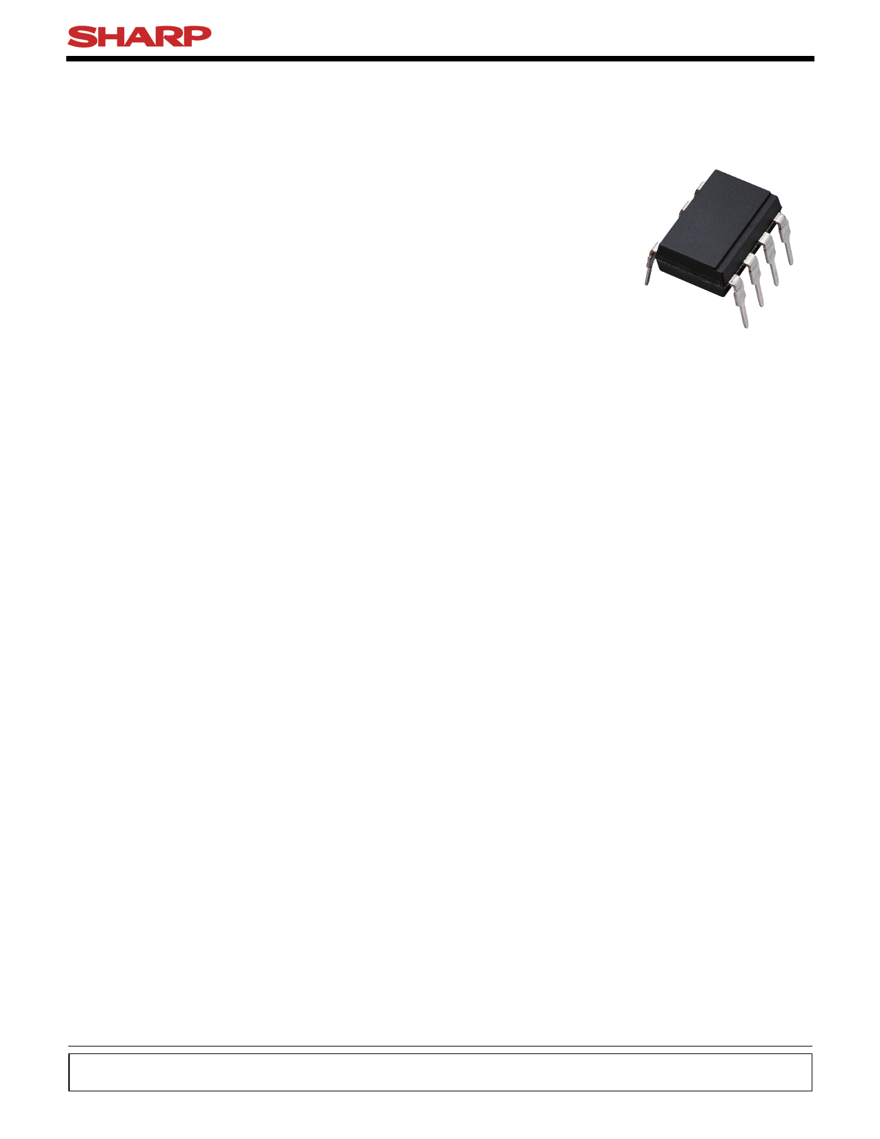
DIP 8pin
Triac output SSR
■ Description
PR26MF1xNSZ Series and PR36MF1xNSZ Series
Solid State Relays (SSR) are an integration of an
infrared emitting diode (IRED), a Phototriac Detector
and a main output Triac. These devices are ideally
suited for controlling high voltage AC loads with solid
state reliability while providing 4.0kV isolation
(Viso(rms)) from input to output.
■ Features
1. Output current, IT(rms)≤0.6A
2. Non-zero crossing functionary
3. 8 pin DIP package (SMT gullwing also available)
4. High repetitive peak off-state voltage
(VDRM : 600V, PR36MF1xNSZ Series)
(VDRM : 400V, PR26MF1xNSZ Series)
5. IFT ranks available (see Model Line-up in this
datasheet)
6. Superior noise immunity (dV/dt : MIN. 100V/µs)
7. Response time, ton : MAX. 100µs
8. High isolation voltage between input and output
(Viso(rms) : 4.0kV)
(
■ Agency approvals/Compliance
1. Recognized by UL508, file No. E94758 (as model No.
R26MF1/R36MF1)
2. Approved by CSA 22.2 No.14, file No. LR63705 (as
model No. R26MF1/R36MF1)
3. Optionary available VDE approved (∗)(DIN EN 60747-5-
2), file No. 40008898 (only for PR36MF1xNSZ Series
as model No. R36MF1)
4. Package resin : UL flammability grade (94V-0)
(∗) DIN EN60747-5-2 : successor standard of DIN VDE0884.
Up to Date code "RD" (December 2003), approval of DIN
VDE0884.
From Date code "S1" (January 2004), approval of DIN
EN60747-5-2.
■ Applications
1. Isolated interface between high voltage AC devices
and lower voltage DC control circuitry.
2. Switching motors, fans, heaters, solenoids, and
valves.
3. Phase or power control in applications such as
lighting and temperature control equipment.
Notice The content of data sheet is subject to change without prior notice.
In the absence of confirmation by device specification sheets, SHARP takes no responsibility for any defects that may occur in equipment using any SHARP
devices shown in catalogs, data books, etc. Contact SHARP in order to obtain the latest device specification sheets before using any SHARP device.
Sheet No.: D4-A00401FEN
1 Date Mar. 31. 2004
© SHARP Corporation Free Datasheet http://www.Datasheet4U.com
1 page 
■ Absolute Maximum Ratings
(Ta=25˚C)
Parameter
Symbol Rating Unit
Input
Output
Forward current
Reverse voltage
RMS ON-state current
Peak one cycle surge current
Repetitive
PR26MF1xNSZ
peak OFF-state voltage PR36MF1xNSZ
IF
VR
IT(rms)
Isurge
VDRM
50 *3
6
0.6 *3
6 *4
400
600
mA
V
A
A
V
*1Isolation voltage
Viso(rms) 4.0
kV
Operating temperature
Topr −25 to +85 ˚C
Storage temperature
*2Soldering temperature
Tstg −40 to +125 ˚C
Tsol 270 *5 ˚C
*1 40 to 60%RH, AC for 1minute, f=60Hz
*2 For 10s
*3 Refer to Fig.1, Fig.2
*4 f=50Hz sine wave
*5 Lead solder plating models: 260˚C
PR26MF1xNSZ Series
PR36MF1xNSZ Series
Soldering area
■ Electro-optical Characteristics
Parameter
Forward voltage
Input
Reverse current
Repetitive peak OFF-state current
ON-state voltage
Output Holding current
Critical rate of rise of OFF-state voltage
Minimum trigger current
Transfer
charac- Isolation resistance
teristics
Turn-on time
Rank 1
Rank 2
Rank 1
Rank 2
Symbol
VF
IR
IDRM
VT
IH
dV/dt
IFT
RISO
ton
Conditions
IF=20mA
VR=3V
VD=VDRM
IT=0.6A
VD=V1/D√=−26·VVDRM
VD=6V, RL=100Ω
DC500V,40 to 60%RH
VD=6V, RL=100Ω, IF=20mA
VD=6V, RL=100Ω, IF=10mA
MIN.
−
−
−
−
−
100
−
−
5×10¹⁰
TYP.
1.2
−
−
−
−
−
−
−
1011
(Ta=25˚C)
MAX. Unit
1.4 V
10 µA
100 µA
3.0 V
25 mA
− V/µs
10 mA
5
−Ω
− − 100 µs
Sheet No.: D4-A00401FEN
5
Free Datasheet http://www.Datasheet4U.com
5 Page 
■ Manufacturing Guidelines
● Soldering Method
Reflow Soldering:
Reflow soldering should follow the temperature profile shown below.
Soldering should not exceed the curve of temperature profile and time.
Please don't solder more than twice.
(˚C)
300 Terminal : 260˚C peak
( package surface : 250˚C peak)
PR26MF1xNSZ Series
PR36MF1xNSZ Series
200
100 Preheat
150 to 180˚C, 120s or less
Reflow
220˚C or more, 60s or less
0
0 1 2 3 4 (min)
Flow Soldering :
Flow soldering should be completed below 270˚C and within 10s.
Preheating is within the bounds of 100 to 150˚C and 30 to 80s.
Please don't solder more than twice.
Hand soldering
Hand soldering should be completed within 3s when the point of solder iron is below 400˚C.
Please don't solder more than twice.
Other notices
Please test the soldering method in actual condition and make sure the soldering works fine, since the impact
on the junction between the device and PCB varies depending on the tooling and soldering conditions.
11
Sheet No.: D4-A00401FEN
Free Datasheet http://www.Datasheet4U.com
11 Page | ||
| Páginas | Total 15 Páginas | |
| PDF Descargar | [ Datasheet PR26MF11NSZF.PDF ] | |
Hoja de datos destacado
| Número de pieza | Descripción | Fabricantes |
| PR26MF11NSZF | Non-Zero Cross type DIP 8pin Triac output SSR | Sharp |
| Número de pieza | Descripción | Fabricantes |
| SLA6805M | High Voltage 3 phase Motor Driver IC. |
Sanken |
| SDC1742 | 12- and 14-Bit Hybrid Synchro / Resolver-to-Digital Converters. |
Analog Devices |
|
DataSheet.es es una pagina web que funciona como un repositorio de manuales o hoja de datos de muchos de los productos más populares, |
| DataSheet.es | 2020 | Privacy Policy | Contacto | Buscar |