|
|
|
PDF BR200 Data sheet ( Hoja de datos )
| Número de pieza | BR200 | |
| Descripción | (BR200 / BR201) POL Converter Module | |
| Fabricantes | Sanken | |
| Logotipo | ||
Hay una vista previa y un enlace de descarga de BR200 (archivo pdf) en la parte inferior de esta página. Total 12 Páginas | ||
|
No Preview Available !
BR200/201
POL Converter Module for 12 V System Intermediate Bus
Features and Benefits
• Industry standard footprint
• Improved soldering: gold-plated pads and side notches
• Synchronized rectifying type stepdown chopper
• High power
• High efficiency:
▫ BR200, 89.9% at VIN = 12 V, VO = 1.5 V, IO = 7 A
▫ BR201, 93.8% at VIN = 12 V, VO = 3.3 V, IO = 7 A
• Operating temperature range: –40°C to 85°C
• Input voltage range: 7 to 14 VDC
• Output voltage: BR200, 0.75 to 1.65 V; BR201, 1.6 to 3.63 V
• Output current range: 0 to 10 A
• Operating frequency: BR200, 300 kHz; BR201, 600 kHz
• Overcurrent protection function
Package: Module
Description
The BR200 and BR201 are thin type POL converter modules
with an industry standard exterior shape and footprint,
responsive to very high speed loads and compatible with
ceramic capacitors.
They can be used as design-free POL converters for a 12 V
system intermediate bus. They can be configured easily,
reducing overall design time, and allowing reuse of designs.
Miniaturization was achieved by high frequency switching
technology, allowing saving space on the application PCB.
Soldering capability has been significantly improved by
adoption of end face through holes.
20.3 × 11.4 × 4.2 mm
Applications:
• Communication devices
• Computer server
• Other low power conversion
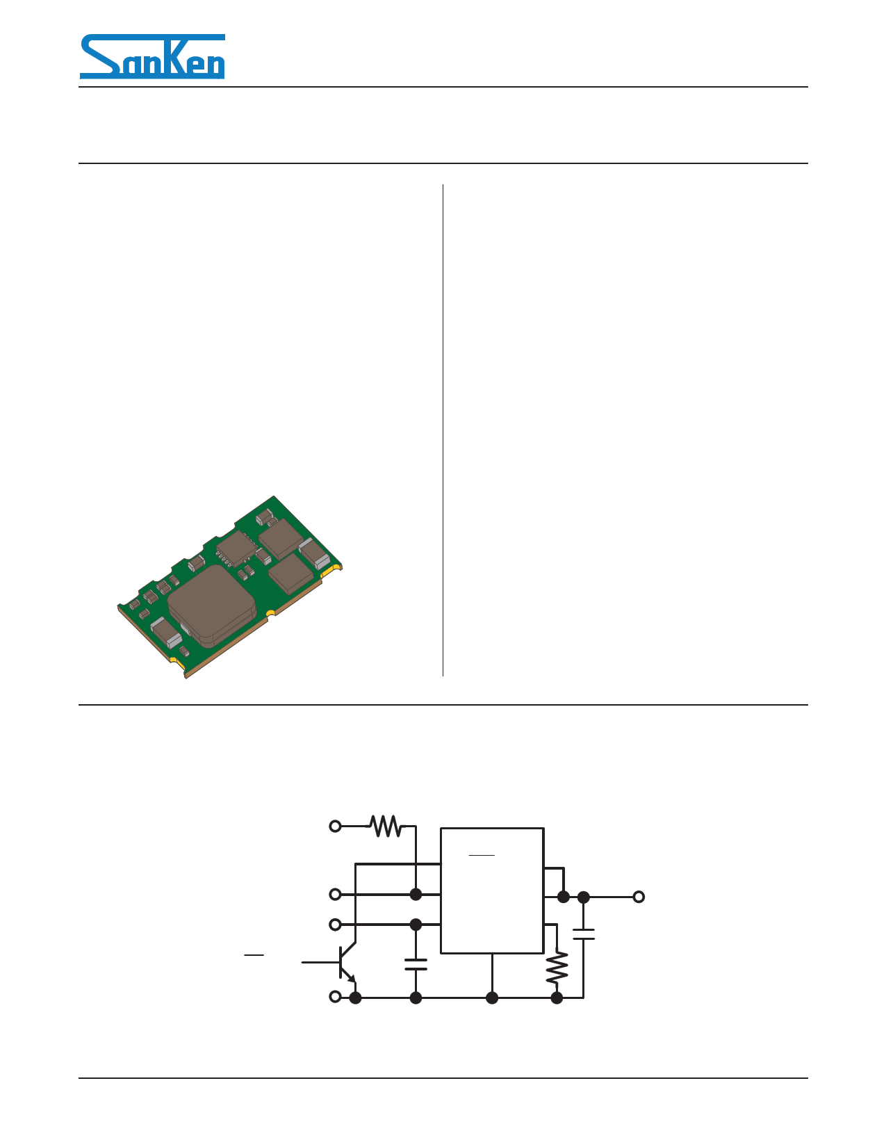
Typical Application Circuit
VPG (5 V)
Power Good
VIN
ON/OFF
GND
BR200/201
ON/OFF VS+
PG VOUT
VIN RTRIM
GND
CIN RTRIM
VOUT
COUT
BR200-DS, Rev. 0.2
February 6, 2013
SANKEN ELECTRIC CO., LTD.
http://www.sanken-ele.co.jp/en/
Free Datasheet http://www.Datasheet4U.com
1 page 
BR200/201
POL Converter Module for 12 V System Intermediate Bus
Performance Characteristics
TA = 25°C
Efficiency versus Output Current
BR200, VOUT = 1.5 V
BR201, VOUT = 3.3 V
Temperature Derating
Measuring condition:
Product soldered directly to 101.6 ×101.6 mm, 1.6 mm thick, 6-layer PCB
PCB is mounted vertically during measurement
Measuring locations
(Centers of top surface
of major components)
BR200, VOUT = 1.5 V, VIN = 12 V
In Still Air
14
12
10
8
6
4
2
0
40.0 50.0 60.0 70.0 80.0
TA (°C)
90.0
BR201, VOUT = 3.3 V, VIN = 12 V
In Still Air
14
12
10
8
6
4
2
0
40.0 50.0 60.0 70.0 80.0
TA (°C)
90.0
Airflow
BR200, VOUT = 1.5 V, VIN = 12 V
1.5 m/s Airflow
14
12
10
8
6
4
2
0
40.0 50.0 60.0 70.0 80.0 90.0
TA (°C)
BR201, VOUT = 3.3 V, VIN = 12 V
1.5 m/s Airflow
14
12
10
8
6
4
2
0
40.0 50.0 60.0 70.0 80.0
TA (°C)
90.0
BR200-DS, Rev. 0.2
SANKEN ELECTRIC CO., LTD.
5
Free Datasheet http://www.Datasheet4U.com
5 Page 
BR200/201
POL Converter Module for 12 V System Intermediate Bus
OPERATING PRECAUTIONS
Because reliability can be affected adversely by improper storage
environments and handling methods, please observe the follow-
ing cautions.
Cautions for Storage
• Ensure that storage conditions comply with the standard
temperature (5°C to 35°C) and the standard relative humidity
(around 40% to 75%); avoid storage locations that experience
extreme changes in temperature or humidity.
• Avoid locations where dust or harmful gases are present and
avoid direct sunlight.
• Reinspect for rust on leads and solderability of products that
have been stored for a long time.
Cautions for Testing and Handling
When tests are carried out during inspection testing and other
standard test periods, protect the products from power surges
from the testing products, shorts between the product pins, and
wrong connections. In addition, avoid tests exceeded ratings.
Electrostatic Discharge
• When handling the products, the operator must be grounded. To
prevent shock hazard, grounded wrist straps should be used and
at least 1 MΩ of resistance from the operator to ground should
be placed near the operator.
• Workbenches where the products are handled should be ground-
ed and be provided with conductive table and floor mats.
• When using measuring equipment such as a curve tracer, the
equipment should be grounded.
• When soldering the products, the head of a soldering irons or
the solder bath must be grounded in order to prevent leak volt-
ages generated by them from being applied to the products.
• The products should always be stored and transported in Sanken
shipping containers or conductive containers, or be wrapped in
aluminum foil.
Cautions for Use
• Do not use the power modules under overload conditions as that
will damage the module and cause a malfunction or failures.
• Use the products within the specified input voltage range.
BR200-DS, Rev. 0.2
SANKEN ELECTRIC CO., LTD.
11
Free Datasheet http://www.Datasheet4U.com
11 Page | ||
| Páginas | Total 12 Páginas | |
| PDF Descargar | [ Datasheet BR200.PDF ] | |
Hoja de datos destacado
| Número de pieza | Descripción | Fabricantes |
| BR200 | (BR200 / BR201) POL Converter Module | Sanken |
| BR201 | (BR200 / BR201) POL Converter Module | Sanken |
| BR2016 | Lithium Coin Batteries | Panasonic |
| BR202 | (BR202 / BR203) POL Converter Module | Sanken |
| Número de pieza | Descripción | Fabricantes |
| SLA6805M | High Voltage 3 phase Motor Driver IC. |
Sanken |
| SDC1742 | 12- and 14-Bit Hybrid Synchro / Resolver-to-Digital Converters. |
Analog Devices |
|
DataSheet.es es una pagina web que funciona como un repositorio de manuales o hoja de datos de muchos de los productos más populares, |
| DataSheet.es | 2020 | Privacy Policy | Contacto | Buscar |