|
|
|
PDF AOZ8001A Data sheet ( Hoja de datos )
| Número de pieza | AOZ8001A | |
| Descripción | Ultra-Low Capacitance TVS Diode Array | |
| Fabricantes | Alpha & Omega Semiconductors | |
| Logotipo | ||
Hay una vista previa y un enlace de descarga de AOZ8001A (archivo pdf) en la parte inferior de esta página. Total 10 Páginas | ||
|
No Preview Available !
AOZ8001A
Ultra-Low Capacitance TVS Diode Array
General Description
The AOZ8001A is a transient voltage suppressor array
designed to protect high speed data lines from ESD and
lightning.
This device incorporates four surge rated, low capacitance
steering diodes and a TVS in a single package. During
transient conditions, the steering diodes direct the
transient to either the positive side of the power supply
line or to ground. They may be used to meet the ESD
immunity requirements of IEC 61000-4-2, Level 4.
The TVS diodes provide effective suppression of ESD
voltages up to ±30kV (air discharge) and ±30kV (contact
discharge).
The AOZ8001A comes in RoHS compliant, SOT-143
package and is rated over a -40°C to +85°C ambient
temperature range. It is compatible with both lead free
and SnPb assembly techniques.
The very small SOT-143 package is ideal for applications
where PCB space is a premium. The small size, low
capacitance and high ESD protection makes it ideal for
protecting high speed video and data communication
interfaces.
Features
● ESD protection for high-speed data lines:
AOZ8001AJI 5V:
– IEC 61000-4-2, level 4 (ESD) immunity test
– ±30kV (air discharge) and ±30kV (contact discharge)
– IEC 61000-4-5 (Lightning) 18A (8/20µs)
– Human Body Model (HBM) ±30kV
AOZ8001AJI 12V:
– IEC61000-4-2, Level 4 (ESD) immunity test
– ±30kV (air discharge) and ±30kV (contact discharge)
– IEC61000-4-5 (Lightning) ±13A (8/20µs)
– Human Body Model (HBM) ±30kV
● Small package saves board space
● Low insertion loss
● Protects two I/O lines
● Low capacitance from IO to Ground: 1.8pF
● Low clamping voltage
● Low operating voltages: 5V, 12V
Applications
● USB 2.0 power and data line protection
● Video graphics cards
● Monitors and flat panel displays
● Digital Video Interface (DVI)
● 10/100/1000 Ethernet
● Notebook computers
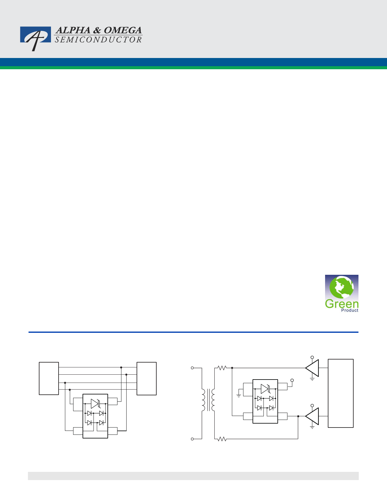
Typical Application
USB Controller
+5V
D+
D-
GND
1
4
USB Controller
+5V
D+
D-
GND
Tip
RJ11
Connector
23
AOZ8001AJI-05
Figure 1. USB 2.0 High Speed Port
Rev. 3.0 October 2010
Ring
www.aosmd.com
+12V
+12V
xDSL
1 Controller
+12V
2
AOZ8001AJI-12
Figure 2. xDSL Application
Page 1 of 10
http://www.Datasheet4U.com
1 page 
AOZ8001A
Application Information
The AOZ8001A TVS is design to protect two data lines
from fast damaging transient over-voltage by clamping it
to a reference. When the transient on a protected data
line exceed the reference voltage the steering diode is
forward bias thus, conducting the harmful ESD transient
away from the sensitive circuitry under protection.
PCB Layout Guidelines
Printed circuit board layout is the key to achieving the
highest level of surge immunity on power and data lines.
The location of the protection devices on the PCB is the
simplest and most important design rule to follow. The
AOZ8001A devices should be located as close as possi-
ble to the noise source. The placement of the AOZ8001A
devices should be used on all data and power lines that
enter or exit the PCB at the I/O connector. In most
systems, surge pulses occur on data and power lines
that enter the PCB through the I/O connector. Placing
the AOZ8001A devices as close as possible to the noise
source ensures that a surge voltage will be clamped
before the pulse can be coupled into adjacent PCB
traces. In addition, the PCB should use the shortest
possible traces. A short trace length equates to low
impedance, which ensures that the surge energy will be
dissipated by the AOZ8001A device. Long signal traces
will act as antennas to receive energy from fields that are
produced by the ESD pulse. By keeping line lengths as
short as possible, the efficiency of the line to act as an
antenna for ESD related fields is reduced. Minimize inter-
connecting line lengths by placing devices with the most
interconnect as close together as possible. The protec-
tion circuits should shunt the surge voltage to either the
reference or chassis ground. Shunting the surge voltage
directly to the IC’s signal ground can cause ground
bounce. The clamping performance of TVS diodes on a
single ground PCB can be improved by minimizing the
impedance with relatively short and wide ground traces.
The PCB layout and IC package parasitic inductances
can cause significant overshoot to the TVS’s clamping
voltage. The inductance of the PCB can be reduced by
using short trace lengths and multiple layers with
separate ground and power planes. One effective
method to minimize loop problems is to incorporate a
ground plane in the PCB design. The AOZ8001A ultra-
low capacitance TVS is designed to protect four high
speed data transmission lines from transient over-volt-
ages by clamping them to a fixed reference. The low
inductance and construction minimizes voltage over-
shoot during high current surges. When the voltage on
the protected line exceeds the reference voltage the
internal steering diodes are forward biased, conducting
the transient
current away from the sensitive circuitry.
Good circuit board layout is critical for the suppression
of ESD induced transients. The following guidelines are
recommended:
1. Place the TVS near the IO terminals or connectors to
restrict transient coupling.
2. Fill unused portions of the PCB with ground plane.
3. Minimize the path length between the TVS and the
protected line.
4. Minimize all conductive loops including power and
ground loops.
5. The ESD transient return path to ground should be
kept as short as possible.
6. Never run critical signals near board edges.
7. Use ground planes whenever possible.
8. Avoid running critical signal traces (clocks, resets,
etc.) near PCB edges.
9. Separate chassis ground traces from components
and signal traces by at least 4mm.
10. Keep the chassis ground trace length-to-width ratio
<5:1 to minimize inductance.
11. Protect all external connections with TVS diodes.
Rev. 3.0 October 2010
www.aosmd.com
Page 5 of 10
5 Page | ||
| Páginas | Total 10 Páginas | |
| PDF Descargar | [ Datasheet AOZ8001A.PDF ] | |
Hoja de datos destacado
| Número de pieza | Descripción | Fabricantes |
| AOZ8001 | Ultra-Low Capacitance TVS Diode Array | Alpha & Omega Semiconductors |
| AOZ8001A | Ultra-Low Capacitance TVS Diode Array | Alpha & Omega Semiconductors |
| Número de pieza | Descripción | Fabricantes |
| SLA6805M | High Voltage 3 phase Motor Driver IC. |
Sanken |
| SDC1742 | 12- and 14-Bit Hybrid Synchro / Resolver-to-Digital Converters. |
Analog Devices |
|
DataSheet.es es una pagina web que funciona como un repositorio de manuales o hoja de datos de muchos de los productos más populares, |
| DataSheet.es | 2020 | Privacy Policy | Contacto | Buscar |