|
|
|
PDF SPE0524 Data sheet ( Hoja de datos )
| Número de pieza | SPE0524 | |
| Descripción | 3-Line ESD Protection Array | |
| Fabricantes | SYNC POWER | |
| Logotipo | ||
Hay una vista previa y un enlace de descarga de SPE0524 (archivo pdf) en la parte inferior de esta página. Total 8 Páginas | ||
|
No Preview Available !
SPE0524
3-Line ESD Protection Array
DESCRIPTION
The SPE0524 are designed by TVS array that is to
protect sensitive electronics from damage or latch-up
due to ESD. They are designed for use in applications
where board space is at a premium. SPE0524 will
protect up to three line, and may be used on lines
where the signal polarities swing above and below
ground.
SPE0524 offer desirable characteristics for board
level protection including fast response time, low
operating and clamping voltage, and no device
degradation.
SPE0524 may be used to meet the immunity
requirements of IEC 61000-4-2, level 4. The small
SOT-143 package makes them ideal for use in
portable electronics such as cell phones, PDA’s,
notebook computers, and digital cameras.
APPLICATIONS
Cellular Handsets and Accessories
Cordless Phone
PDA
Notebooks and Handhelds
Portable Instrumentation
Digital Cameras
MP3 Player
FEATURES
Transient protection for data lines to
IEC 61000-4-2 (ESD) ±15kV (air), ±8kV
(contact)
IEC 61000-4-4 (EFT) 40A (5/50ns)
Protects four I/O lines
Working voltage: 5V
Low leakage current
Low operating and clamping voltages
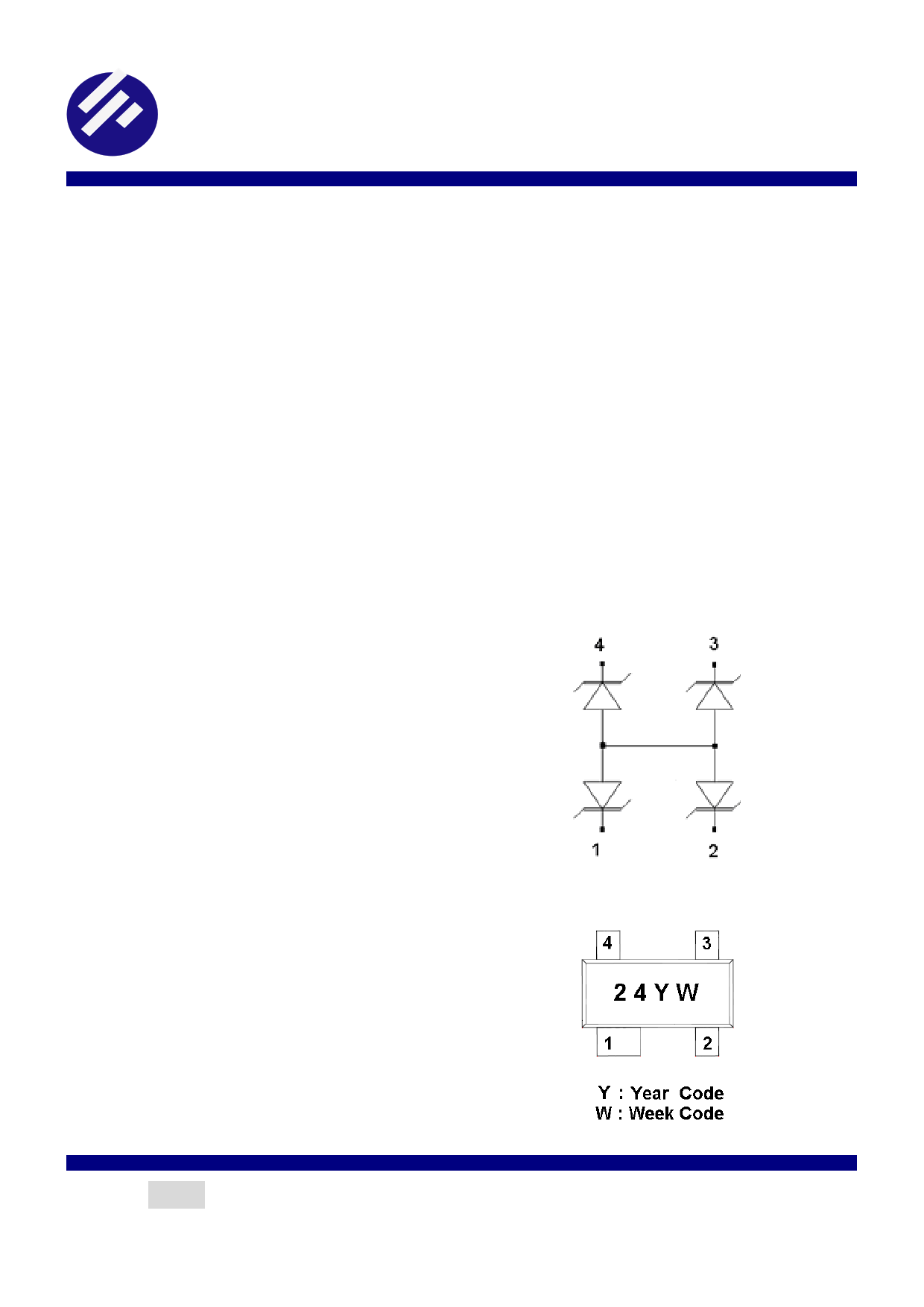
PIN CONFIGURATION ( SOT-143-A)
PART MARKING
2012/08/14 Ver.3
Page 1
http://www.Datasheet4U.com
1 page 
SPE0524
3-Line ESD Protection Array
APPLICATION NOTE
Device Connection for Protection of Four Data Lines
SPE0524 is designed to protect up to three data lines. The device is connected as follows:
1. The TVS protection of four I/O lines is achieved by connecting pins 1, 2, 4. Pin 3 are connected to ground. The
ground connection should be made directly to the ground plane for best results. The path length is kept as short
as possible to reduce the effects of parasitic inductance.
Circuit Board Layout Recommendations for Suppression of ESD
Good circuit board layout is critical for the suppression of ESD induced transients. The following guidelines are
recommended:
1. Place the TVS near the input terminals or connectors to restrict transient coupling.
2. Minimize the path length between the TVS and the protected line.
3. Minimize all conductive loops including power and ground loops.
4. The ESD transient return path to ground should be kept as short as possible.
5. Never run critical signals near board edges.
6. Use ground planes whenever possible.
2012/08/14 Ver.3
Page 5
5 Page | ||
| Páginas | Total 8 Páginas | |
| PDF Descargar | [ Datasheet SPE0524.PDF ] | |
Hoja de datos destacado
| Número de pieza | Descripción | Fabricantes |
| SPE0521 | Single-Line ESD Protection Array | SYNC POWER |
| SPE0521D52RG | Single-Line ESD Protection Array | SYNC POWER |
| SPE0521D52RGB | Single-Line ESD Protection Array | SYNC POWER |
| SPE0522 | 2-Line ESD Protection Array | SYNC POWER |
| Número de pieza | Descripción | Fabricantes |
| SLA6805M | High Voltage 3 phase Motor Driver IC. |
Sanken |
| SDC1742 | 12- and 14-Bit Hybrid Synchro / Resolver-to-Digital Converters. |
Analog Devices |
|
DataSheet.es es una pagina web que funciona como un repositorio de manuales o hoja de datos de muchos de los productos más populares, |
| DataSheet.es | 2020 | Privacy Policy | Contacto | Buscar |