|
|
|
PDF MP2367 Data sheet ( Hoja de datos )
| Número de pieza | MP2367 | |
| Descripción | 340KHz Step-Down Converter | |
| Fabricantes | MPS | |
| Logotipo | ||
Hay una vista previa y un enlace de descarga de MP2367 (archivo pdf) en la parte inferior de esta página. Total 11 Páginas | ||
|
No Preview Available !
TM MP2367
3A, 28V, 340KHz
Step-Down Converter
The Future of Analog IC Technology TM
PRELIMINARY SPECIFICATIONS SUBJECT TO CHANGE – INTERNAL USE ONLY
DESCRIPTION
The MP2367 is a monolithic step down
regulator. The device integrates 130mΩ
MOSFET that provides 3A continuous load
current over a wide operating input voltage of
4.75V to 28V. Current mode control provides
fast transient response and cycle-by-cycle
current limit.
An adjustable soft-start prevents inrush current
at turn-on. In shutdown mode, the supply
current drops to 1µA.
This device, available in an 8-pin SOIC
package, provides a very compact system
solution with minimal reliance on external
components.
EVALUATION BOARD REFERENCE
Board Number
EV2367DN-00A
Dimensions
2.0”X x 1.5”Y x 0.5”Z
FEATURES
• 3A Output Current
• Wide 4.75V to 28V Operating Input Range
• Integrated Power MOSFET Switches
• Output Adjustable from 0.8V to 25V
• Up to 95% Efficiency
• Programmable Soft-Start
• Stable with Low ESR Ceramic Output Capacitors
• Fixed 340KHz Frequency
• Cycle-by-Cycle Over Current Protection
• Input Under Voltage Lockout
• Thermally Enhanced 8-Pin SOIC Package
APPLICATIONS
• Distributed Power Systems
• Pre-Regulator for Linear Regulators
• Notebook Computers
“MPS” and “The Future of Analog IC Technology” are Trademarks of Monolithic
Power Systems, Inc.
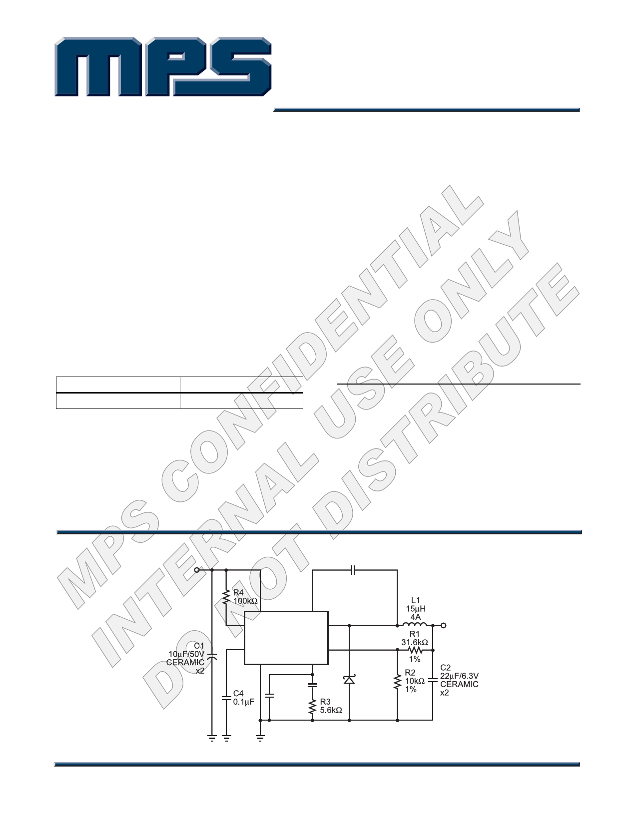
TYPICAL APPLICATION
INPUT
4.75V to 28V
C5
10nF
21
7
IN
EN
BS
SW
3
MP2367
8 SS
FB 5
GND
COMP
46
C6
(optional)
C3
3.3nF
D1
B330A
OUTPUT
3.3V
3A
MP2367_TAC01
MP2367 Rev. 0.2
1/11/2006
www.MonolithicPower.com
MPS Proprietary Information. Unauthorized Photocopy and Duplication Prohibited.
© 2006 MPS. All Rights Reserved.
1
1 page 
TM
MP2367 – 3A, 28V, 340KHz STEP-DOWN CONVERTER
PRELIMINARY SPECIFICATIONS SUBJECT TO CHANGE – INTERNAL USE ONLY
APPLICATIONS INFORMATION
COMPONENT SELECTION
Setting the Output Voltage
The output voltage is set using a resistive
voltage divider from the output voltage to FB
pin. The voltage divider divides the output
voltage down to the feedback voltage by the
ratio:
VFB
=
VOUT
R2
R1+ R2
Thus the output voltage is:
VOUT
=
0.8 ×
R1 + R2
R2
Where VFB is the feedback voltage and VOUT is
the output voltage.
A typical value for R2 can be as high as 100kΩ,
but a typical value is 10kΩ. Using that value, R1
is determined by:
R1 = 12.5 × (VOUT − 0.8)(kΩ)
For example, for a 3.3V output voltage, R2 is
10kΩ, and R1 is 31.3kΩ.
Inductor
The inductor is required to supply constant
current to the output load while being driven by
the switched input voltage. A larger value
inductor will result in less ripple current that will
result in lower output ripple voltage. However,
the larger value inductor will have a larger
physical size, higher series resistance, and/or
lower saturation current. A good rule for
determining the inductance to use is to allow
the peak-to-peak ripple current in the inductor
to be approximately 30% of the maximum
switch current limit. Also, make sure that the
peak inductor current is below the maximum
switch current limit. The inductance value can
be calculated by:
L
=
VOUT
fS × ∆I
× ⎜⎜⎝⎛1 −
VOUT
VIN
⎟⎟⎠⎞
Where VIN is the input voltage, fS is the 340KHz
switching frequency, and ∆IL is the peak-to-
peak inductor ripple current.
Choose an inductor that will not saturate under
the maximum inductor peak current. The peak
inductor current can be calculated by:
ILP
= ILOAD
+
VOUT
2 × fS × L
× ⎜⎜⎝⎛1−
VOUT
VIN
⎟⎟⎠⎞
Where ILOAD is the load current.
Optional Schottky Diode
During the transition between high-side switch
and low-side switch, the body diode of the low-
side power MOSFET conducts the inductor
current. The forward voltage of this body diode
is high. An optional Schottky diode may be
paralleled between the SW pin and GND pin to
improve overall efficiency.
Input Capacitor
The input current to the step-down converter is
discontinuous, therefore a capacitor is required
to supply the AC current to the step-down
converter while maintaining the DC input
voltage. Use low ESR capacitors for the best
performance. Ceramic capacitors are preferred,
but tantalum or low-ESR electrolytic capacitors
may also suffice. Choose X5R or X7R
dielectrics when using ceramic capacitors.
Since the input capacitor (C1) absorbs the input
switching current it requires an adequate ripple
current rating. The RMS current in the input
capacitor can be estimated by:
IC1 = ILOAD ×
VOUT
VIN
×⎜⎜⎛1−
⎝
VOUT
VIN
⎟⎞
⎟
⎠
The worst-case condition occurs at VIN = 2VOUT,
where IC1 = ILOAD/2. For simplification, choose
the input capacitor whose RMS current rating
greater than half of the maximum load current.
MP2367 Rev. 0.2
1/11/2006
www.MonolithicPower.com
MPS Proprietary Information. Unauthorized Photocopy and Duplication Prohibited.
© 2006 MPS. All Rights Reserved.
5
5 Page 
TM
MP2367 – 3A, 28V, 340KHz STEP-DOWN CONVERTER
PRELIMINARY SPECIFICATIONS SUBJECT TO CHANGE – INTERNAL USE ONLY
PACKAGE INFORMATION
SOIC8N (EXPOSED PAD)
NOTICE: The information in this document is subject to change without notice. Please contact MPS for current specifications.
Users should warrant and guarantee that third party Intellectual Property rights are not infringed upon when integrating MPS
products into any application. MPS will not assume any legal responsibility for any said applications.
MP2367 Rev. 0.2
1/11/2006
www.MonolithicPower.com
MPS Proprietary Information. Unauthorized Photocopy and Duplication Prohibited.
© 2006 MPS. All Rights Reserved.
11
11 Page | ||
| Páginas | Total 11 Páginas | |
| PDF Descargar | [ Datasheet MP2367.PDF ] | |
Hoja de datos destacado
| Número de pieza | Descripción | Fabricantes |
| MP2360 | 1.4MHz Step-Down Converter | MPS |
| MP2361 | 1.4MHz Step-Down Converter | MPS |
| MP2362 | 380KHz Step-Down Converter | MPS |
| MP2363 | 365KHz Step-Down Converter | MPS |
| Número de pieza | Descripción | Fabricantes |
| SLA6805M | High Voltage 3 phase Motor Driver IC. |
Sanken |
| SDC1742 | 12- and 14-Bit Hybrid Synchro / Resolver-to-Digital Converters. |
Analog Devices |
|
DataSheet.es es una pagina web que funciona como un repositorio de manuales o hoja de datos de muchos de los productos más populares, |
| DataSheet.es | 2020 | Privacy Policy | Contacto | Buscar |