|
|
|
PDF MAX7370 Data sheet ( Hoja de datos )
| Número de pieza | MAX7370 | |
| Descripción | 8 x 8 Key-Switch Controller and LED Driver/GPIOs | |
| Fabricantes | Maxim Integrated | |
| Logotipo | ||
Hay una vista previa y un enlace de descarga de MAX7370 (archivo pdf) en la parte inferior de esta página. Total 37 Páginas | ||
|
No Preview Available !
EVALUATION KIT AVAILABLE
MAX7370
8 x 8 Key-Switch Controller and LED Driver/GPIOs
with I2C Interface and High Level of ESD Protection
General Description
Features
The MAX7370 I2C-interfaced peripheral provides micro-
processors with management of up to 64 key switches,
with optional GPIO and PWM-controlled LED drivers.
The key-switch drivers interface with metallic or resistive
switches with on-resistances up to 5kI. Key inputs are
monitored statically, not dynamically, to ensure low-EMI
operation. The IC features autosleep and autowake
modes to further minimize the power consumption of
the device. The autosleep feature puts the device in a
low-power state (1µA typ) after a timeout period. The
autowake feature configures the device to return to
normal operating mode from sleep upon a keypress.
The key controller debounces and maintains a FIFO
buffer of keypress and release events (including auto-
repeat, if enabled). An interrupt (INT) output can be
configured to alert keypresses, as they occur, or at the
maximum rate.
The same index rows and columns in the device can be
used as a direct logic-level translator.
If the device is not used for key-switch control, all
keyboard pins can be used as GPIOs. Each GPIO can
be programmed to one of the two externally applied
logic voltage levels. Four column ports (COL7–COL4)
can also be configured as LED drivers that feature
constant-current and PWM intensity control. The maximum
constant-current level for each open-drain LED port is
20mA. The intensity of the LED on each open-drain port
can be individually adjusted through a 256-step PWM
control.
The device is offered in a 24-pin (3.5mm x 3.5mm) TQFN
package with an exposed pad, and small 25-bump
(2.159mm x 2.159mm) wafer-level package (WLP) for
cell phones, pocket PCs, and other portable consumer
electronic applications.
The device operates over the -40°C to +85°C extended
temperature range.
Applications
Cell Phones
Notebooks
PDAs
Handheld Games
Portable Consumer Electronics
For related parts and recommended products to use with this part,
refer to www.maximintegrated.com/MAX7370.related.
S Monitors Up to 64 Keys
S Integrated High-ESD Protection
±8kV IEC 61000-4-2 Contact Discharge
±15kV IEC 61000-4-2 Air-Gap Discharge
S Keyscan Uses Static Matrix Monitoring for
Low-EMI Operation
S Four LED Driver Pins on COL7–COL4
S 5V Tolerant, Open-Drain I/O Ports Capable of
Constant-Current LED Drive
S 256-Step PWM Individual LED Intensity-Control
Accuracy
S Individual LED Blink Rates and Common LED
Fade In/Out Rates from 256ms to 4096ms
S FIFO Queues Up to 16 Debounced Key Events
S User-Configurable Keypress and Release
Debounce Time (2ms to 32ms)
S Key-Switch Interrupt (INT) on Each Debounced
Event/FIFO Level, or End-of-Definable Time Period
S 1.62V to 3.6V Operating Supply Voltage
S Individually Programmable GPIOs to Two Logic
Levels
S 8-Channel Individual Programmable Level
Translators
S Provides Optional GPIOs on all ROW_ and COL_
Pins
S Supports Hot Insertion
S 400kbps, 5.5V Tolerant I2C Serial Interface with
Selectable Bus Timeout
Ordering Information appears at end of data sheet.
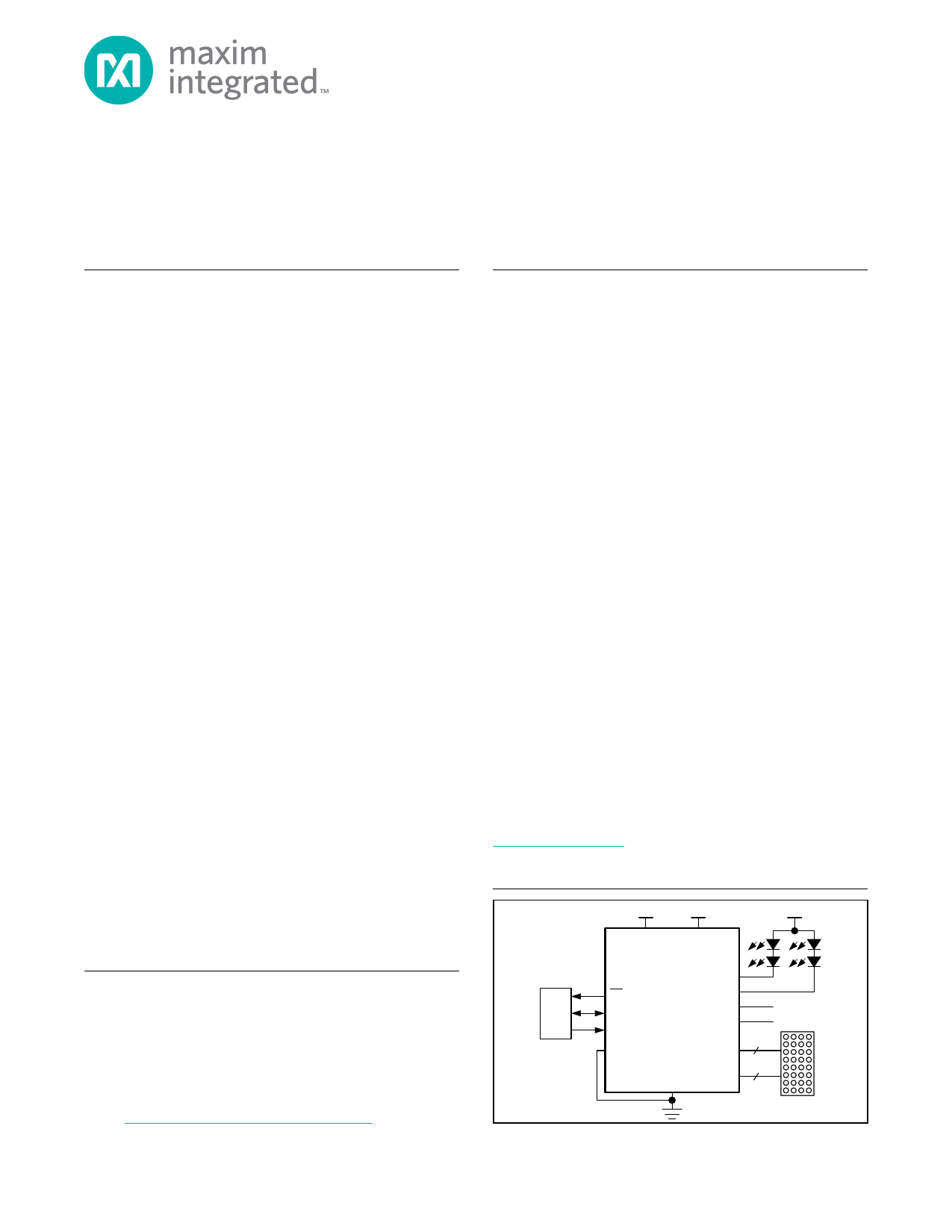
Typical Operating Circuit
+1.8V
VCC
+2.6V
VLA
+5V
MAX7370 COL4
INT
MCU SDA
SCL
COL5
COL6
COL7
I/O
I/O
AD0 ROW[0:7] 8
GND COL[0:3] 4
32 KEYS
For pricing, delivery, and ordering information, please contact Maxim Direct
at 1-888-629-4642, or visit Maxim’s website at www.maximintegrated.com.
19-5950; Rev 1; 3/12
1 page 
MAX7370
8 x 8 Key-Switch Controller and LED Driver/GPIOs
with I2C Interface and High Level of ESD Protection
Typical Operating Characteristics
(VCC = 2.5V, VLA = 2.5V, TA = +25NC, unless otherwise noted.)
GPO OUTPUT LOW VOLTAGE
vs. SINK CURRENT (COL7–COL4)
120
VCC = 2.4V
100 TA = +85°C
80
TA = +25°C
60
GPO OUTPUT LOW VOLTAGE
vs. SINK CURRENT (COL7–COL4)
120
VCC = 3.0V
100
TA = +85°C
80
60 TA = +25°C
GPO OUTPUT LOW VOLTAGE
vs. SINK CURRENT (COL7–COL4)
120
VCC = 3.6V
100
TA = +85°C
80
60 TA = +25°C
40 40 40
20 TA = -40°C
0
0 2 4 6 8 10 12 14 16 18 20
SINK CURRENT (mA)
SUPPLY CURRENT vs. SUPPLY VOLTAGE
60
AUTOSLEEP = OFF
55 TA = +85°C
50
TA = +25°C
45
40
TA = -40°C
35
30
1.6 1.8 2.0 2.2 2.4 2.6 2.8 3.0 3.2 3.4 3.6
SUPPLY VOLTAGE (V)
20 TA = -40°C
0
0 2 4 6 8 10 12 14 16 18 20
SINK CURRENT (mA)
KEY-SWITCH SOURCE CURRENT
vs. SUPPLY VOLTAGE
27.0
VCOL0 = 0V TA = +85°C
26.5
26.0
25.5
TA = +25°C
25.0
24.5
TA = -40°C
24.0
1.6 1.8 2.0 2.2 2.4 2.6 2.8 3.0 3.2 3.4 3.6
SUPPLY VOLTAGE (V)
20 TA = -40°C
0
0 2 4 6 8 10 12 14 16 18 20
SINK CURRENT (mA)
SLEEP-MODE SUPPLY CURRENT
vs. SUPPLY VOLTAGE
1.8
1.6 TA = +85°C
1.4
1.2
1.0 TA = +25°C
0.8
0.6
0.4
0.2 TA = -40°C
0
1.6 1.8 2.0 2.2 2.4 2.6 2.8 3.0 3.2 3.4 3.6
SUPPLY VOLTAGE (V)
CONSTANT-CURRENT GPIO OUTPUT SINK
CURRENT vs. OUTPUT VOLTAGE (COL7–COL4)
25
VCC = 2.4V
TA = +85°C
20
TA = +25°C
15 TA = -40°C
CONSTANT-CURRENT GPIO OUTPUT SINK
CURRENT vs. OUTPUT VOLTAGE (COL7–COL4)
25
VCC = 3.0V
TA = +85°C
20
TA = +25°C
15 TA = -40°C
CONSTANT-CURRENT GPIO OUTPUT SINK
CURRENT vs. OUTPUT VOLTAGE (COL7–COL4)
25
VCC = 3.6V
TA = +85°C
20
TA = +25°C
15 TA = -40°C
10 10 10
555
0
0 0.5 1.0 1.5 2.0 2.5 3.0
OUTPUT VOLTAGE (V)
Maxim Integrated
0
0 0.5 1.0 1.5 2.0 2.5 3.0
OUTPUT VOLTAGE (V)
0
0 0.5 1.0 1.5 2.0 2.5 3.0
OUTPUT VOLTAGE (V)
5
5 Page 
MAX7370
8 x 8 Key-Switch Controller and LED Driver/GPIOs
with I2C Interface and High Level of ESD Protection
the frequency at which the key-repeat code is entered
into the FIFO thereafter. The key being pressed is not
entered again into the FIFO. Bit D7 specifies whether
the autorepeat function is enabled with 0, denoting
autorepeat disabled, and 1, denoting autorepeat
enabled. Bits D[3:0] specify the autorepeat delay in
terms of debounce cycles, ranging from eight debounce
cycles to 128 debounce cycles. See Table 11. Bits D[6:4]
specify the autorepeat rate or frequency ranging from
4–32 debounce cycles.
Only one autorepeat code is entered into the FIFO,
regardless of the number of keys pressed. The autore-
peat code continues to be entered in the FIFO at the
frequency set by bits D[3:0] until another key event is
recorded. Following the key-release event, if any keys are
still pressed, the device restarts the autorepeat sequence.
Autosleep Register (0x06)
Autosleep puts the device in sleep mode to draw minimal
current. When enabled, the device enters sleep mode
if no keys are pressed for the autoshutdown time. See
Table 12.
Key-Switch Array Size Register (0x30)
Bits D[7:4] set the row size of the key-switch array, and
bits D[3:0] set the column size of the key-switch array.
See Table 13. Set the bits to 0 if no key switches are
used. The key-switch array should be connected begin-
ning at ROW0 and COL0. If not used as a key-switch
matrix pin, then the pin can function as a GPIO port.
Key-Switch Sleep Mode
In sleep mode, the device draws minimal current. Switch-
matrix current sources are turned off and pulled up to
VCC. When autosleep is enabled, key-switch inactivity
for a period longer than the autosleep time puts the part
into sleep mode (FIFO data is maintained). Writing a 1 to
D7 or a keypress can take the device out of sleep mode.
Bit D7 in the configuration register gives the sleep-mode
status and can be read any time.
Autowake
Keypresses initiate autowake and the device goes into
operating mode. Keypresses that autowake the device
are not lost. When a key is pressed while the device is in
sleep mode, all analog circuitry, including switch-matrix
current sources, turn on in 2ms. The initial key needs to
be pressed for 2ms plus the debounce time to be stored
in the FIFO. Write a 0 to bit D1 in the configuration regis-
ter (0x01) to disable autowake.
FIFO Overflow
The FIFO overflow status occurs when the FIFO is full
(16 bytes) and additional events occur. If key release is
disabled, then the FIFO overflow status occurs when the
FIFO is full and not upon additional key events. When
the FIFO is overflowed, the first byte read from the FIFO
buffer is the overflow byte (0x7F). The order of the
original 16 bytes of event data is preserved, but further
events could be lost. When the FIFO is full, if the 18th
key event is a key release, then the FIFO overflow status
is removed.
GPIOs
The device has 16 GPIO ports, four of which have LED
control functions. The ports can be used as logic inputs
or logic outputs. COL7–COL4 are also configurable as
constant-current PWM LED drivers. Each port’s logic
level is referenced to VCC or VLA. The GPIO ports’ inputs
can also be debounced. When in PWM mode, the ports
are set up to start their PWM cycle in 45N phase incre-
ments. This prevents large current spikes on the LED
supply voltage when driving multiple LEDs.
LED Driver Enable Register (0x31)
Bits D[3:0] correspond to COL7–COL4 on the device.
Set the corresponding bit to 1 for enabling the LED driver
circuitry and 0 for normal GPIO function. See Table 14.
GPIO Direction 1 and 2 Registers (0x34, 0x35)
These registers configure the pins as an input or an output
port. GPIO Direction 1 register bits D[7:0] correspond with
ROW7–ROW0. See Table 15. GPIO Direction 2 register
bits D[7:0] correspond with COL7–COL0. See Table 16.
Set the corresponding bit to 0 to configure as input and 1
to configure as output.
When the port is initially programmed as an input, there
is a delay of one debounce period prior to detecting
a transition on the input port. This is to prevent a false
interrupt from occurring when changing a port from an
output to an input.
Maxim Integrated
11
11 Page | ||
| Páginas | Total 37 Páginas | |
| PDF Descargar | [ Datasheet MAX7370.PDF ] | |
Hoja de datos destacado
| Número de pieza | Descripción | Fabricantes |
| MAX737 | -5V /-12V /-15V / and Adjustable Inverting Current-Mode PWM Regulators | Maxim Integrated |
| MAX7370 | 8 x 8 Key-Switch Controller and LED Driver/GPIOs | Maxim Integrated |
| MAX7370ETG | 8 x 8 Key-Switch Controller and LED Driver/GPIOs | Maxim Integrated |
| MAX7370EWA | 8 x 8 Key-Switch Controller and LED Driver/GPIOs | Maxim Integrated |
| Número de pieza | Descripción | Fabricantes |
| SLA6805M | High Voltage 3 phase Motor Driver IC. |
Sanken |
| SDC1742 | 12- and 14-Bit Hybrid Synchro / Resolver-to-Digital Converters. |
Analog Devices |
|
DataSheet.es es una pagina web que funciona como un repositorio de manuales o hoja de datos de muchos de los productos más populares, |
| DataSheet.es | 2020 | Privacy Policy | Contacto | Buscar |