|
|
|
PDF EUP8075JIR1 Data sheet ( Hoja de datos )
| Número de pieza | EUP8075JIR1 | |
| Descripción | USB-Compliant Li-Ion Battery Charger Integrated | |
| Fabricantes | Eutech Microelectronics | |
| Logotipo | ||
Hay una vista previa y un enlace de descarga de EUP8075JIR1 (archivo pdf) en la parte inferior de esta página. Total 14 Páginas | ||
|
No Preview Available !
EUP8075
尔 USB-Compliant Li-Ion Battery Charger
Integrated with System Power-Path Management
DESCRIPTION
The EUP8075 series of devices are highly integrated
Li-ion linear chargers and system power path management
devices targeted at space-limited portable applications.
The devices operate from either a USB port or AC adapter.
The high input voltage range with input overvoltage
protection supports low-cost unregulated adapters.
The EUP8075 offer DC supply power-path management
with autonomous power-source selection, power FETs and
current sensors, high-accuracy current and voltage
regulation, charge status, and charge termination, in a
single monolithic device.
The EUP8075 power the system while independently
charging the battery. This feature reduces the charge and
discharge cycles on the battery, allows for proper charge
termination and allows the system to run with an absent or
defective battery pack. This feature also allows for the
system to instantaneously turn on from an external power
source in the case of a deeply discharged battery pack. The
IC design is focused on supplying continuous power to the
system when available from the AC adapter or battery
sources.
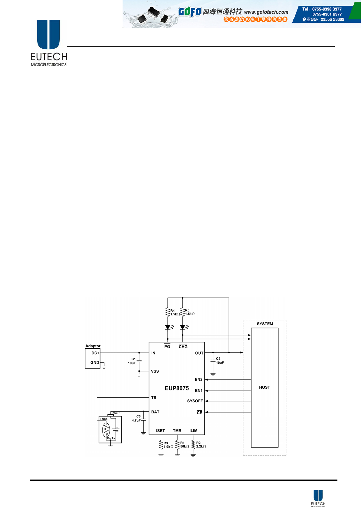
Typical Application Circuit
FEATURES
z Integrated Power-Path Management Feature
Simultaneously and Independently Powers the
System and Charges the Battery
z Integrated USB Charge Control with Selectable
100mA and 500mA Maximum Input Current
Ensures Compliance to USB-IF Standard
z Supports Up to 1.4 Amps Charge Current
z 24V Input Rating
z Thermal Regulation for Charge Control
z Programmable Pre-Charge and Fast-Charge Safety
Timers
z Reverse Current, Short-Circuit, and Thermal
Protections
z Status Indicator-Charging, Done, Power Good
z 3mm × 3mm TQFN-16 Package
z RoHS Compliant and 100% Lead (Pb)-Free
Halogen-Free
APPLICATION
z Smart Phones and PDA
z MP3 Players
z Digital Cameras and Handheld Devices
z Internet Appliances
DS8075 Ver1.0 Apr. 2010
Figure 1.
1
1 page 
EUP8075Tel: 0755-8398 3377 / 135 9011 2223 http://www.gofotech.com
Absolute Maximum Ratings
Input voltage IN(DC voltage with respect to VSS )------------------------------------------- -0.3V to 24V
Input Voltage on BAT, CE , PG , EN2, OUT, ISET, EN1, CHG , TS, ILIM, SYSOFF, TMR
(all DC Voltages VSS) ------------------------------------------------------------------------------ -0.3V to 7V
Input Current ------------------------------------------------------------------------------------------------ 1.6A
Output Current (OUT pin) --------------------------------------------------------------------------------- 1.6A
Output Current (BAT) -------------------------------------------------------------------------------------- 1.4A
Output Sink Current ( PG , CHG ) ------------------------------------------------------------------------ 15mA
Junction temperature range, TJ -------------------------------------------------------------------------- 150°C
Storage temperature range, Tstg ------------------------------------------------------------- -65°C to 150°C
Lead temperature (soldering, 10s) -------------------------------------------------------------------- 260°C
Recommended Operating Conditions
Min.
Max. Unit
Supply voltage, VIN
4.35 24 V
Operating junction temperature range, TJ
-40 125 °C
Electrical Characteristics
over junction temperature range (0°C ≤ TA ≤85°C) and the recommended supply voltage range (unless otherwise noted).
SYMBOLE
PARAMETER
TEST CONDITIONS
MIN
EUP8075
TYP
MAX
UNIT
INPUT BIAS CURRENTS
ICC(SPLY)
Active supply current, IN pin
≠CE =Low, VIN=6V, No Load on OUT pin,
VBAT>VO(BAT_REG) (EN1,EN2) (HI, HI)
1 1.5 mA
V(SLPENT)
Sleep-mode entry threshold
VBAT=4V, VIN: 4.4V→ 3.9V
60 mV
V(SLPEXIT)
Sleep-mode exit threshold
Input power detected
VBAT=4V, VIN: 3.9V→ 4.4V
IIN
VOVP
IBAT(PDWN)
Standby current into IN pin
EN1=High, EN2=High, VIN=6V
Input overvoltage protection threshold VIN: 5V → 7V
Sleep current into BAT pin
CE =Low or HI, input power not detected, No load
on OUT pin
VIN(DPM)
EN2=0, EN1=X
OUT PIN-VOLTAGE REGULATION
VO(REG)
Output pin voltage regulation
VIN>VOUT+VDO
OUT PIN- DPPM REGULATION
VDPPM
BAT PIN CHARGING-PRECHARGE
V(LOWV)
Precharge to fast-charge transition
K(PRECHG)
Precharge current factor
BAT PIN CHARGING-CURRENT REGULATION
6.4
4.55
5.3
4.2
2.9
70
160
6.6
4.65
5.5
4.3
3
96
IO(BAT)
AC battery charge current range (1)
VI (BAT) > V(LOWV), EN2=High, EN1=Low
IO(BAT) = (K(SET) / RSET),
400 1000
K(SET)
Charge current factor
USB MODE INPUT CURRENT LIMIT
IINmax
Maximum input current
KILIM
IINmax
Maximum input current factor
Programmable input current limit
range
EN1=Low, EN2=Low
EN1=High, EN2=Low
EN2=High, EN1=Low
EN2=High, EN1=Low
840 962
70 90
390 440
KILIM /RILIM
1650
200
250
6.9
7
4.8
5.6
4.4
3.1
116
1400
1070
100
500
1500
mV
µA
V
µA
V
V
V
V
AΩ
mA
AΩ
mA
A
AΩ
mA
DS8075 Ver1.0 Apr. 2010
5
5 Page 
EUP8075Tel: 0755-8398 3377 / 135 9011 2223 http://www.gofotech.com
Dynamic Power-Path Management (DPPM)
The theory of operation is the same as described in
CASE 1, except that Q1 is restricted to the USB current
level selected by the EN1 pin.
With a source connected, the power-path management
circuitry of the EUP8075 monitors the input current
continuously. The OUT output for the EUP8075 is
regulated to a fixed voltage (VO(REG)). The current into IN
is shared between charging the battery and powering the
system load at OUT. The EUP8075 has internal
selectable current limits of 100mA (USB100) and
500mA (USB500) for charging from USB ports, as well
as a resistor- programmable input current limit.
The input current limit selection is controlled by the state
of the EN1 and EN2 pins as shown in Table 1. When
using the resistor-programmable current limit, the input
current limit is set by the value of the resistor connected
from the ILIM pin to VSS, and is given by the equation:
I IN−MAX
=
K ILIM
R ILIM
(1)
Battery Temperature Monitoring
The EUP8075 continuously monitors battery temperature
by measuring the voltage between the TS and VSS pins.
An internal current source provides the bias for
most-common 10kΩ negative-temperature coefficient
thermistors (NTC) (see Figure 6). The device compares
the voltage on the TS pin against the internal V(LTF) and
V(HTF) thresholds to determine if charging is allowed.
Once a temperature outside the V(LTF) and V(HTF)
thresholds is detected, the device immediately suspends
the charge. The device suspends charge by turning off the
power FET and holding the timer value (i.e., timers are
not reset). Charge is resumed when the temperature
returns to the normal range. However, the user may
increase the range by adding two external resistors. See
Figure 7.
Figure 6. TS Pin Configuration
Figure 7. TS Pin Thresholds
Battery Pre-Conditioning
During a charge cycle, if the battery voltage is below the
V(LOWV) threshold, the EUP8075 applies a precharge
current, IO(PRECHG), to the battery. This feature revives
deeply discharged cells. The resistor connected between
the ISET and VSS, RSET, determines the precharge rate.
The K(SET) parameters are specified in the specifications
table. Note that this applies to both AC-mode and
USB-mode charging.
I O(PRECHG )
=
K (PRECHG )
R SET
(2)
The EUP8075 activates a safety timer, t(PRECHG), during
the conditioning phase. If V(LOWV) threshold is not
reached within the timer period, the EUP8075 turns off
the charger and enunciates FAULT on the CHG . The
timeout is extended if the charge current is reduced by
DPPM or thermal regulation.
Battery Charge Current
The EUP8075 offers on-chip current regulation with
programmable set point. The resistor connected between
the ISET and VSS, RSET, determines the charge level.
The charge level may be reduced to give the system
priority on input current (see DPPM). The K(SET)
parameters are specified in the specifications table.
IO(BAT )
=
K (SET )
R SET
(3)
When powered from a USB port, the input current
available (0.1A/0.5A) is typically less than the
programmed (ISET) charging current, and therefore, the
DPPM feature attempts to keep the output from being
pulled down by reducing the charging current.
Battery Voltage Regulation
The voltage regulation feedback is through the BAT pin.
This input is tied directly to the positive side of the
battery pack. The EUP8075 monitors the battery-pack
voltage between the BAT and VSS pins. When the
battery voltage rises to the VO(BAT-REG) threshold, the
voltage regulation phase begins and the charging current
begins to taper down.
DS8075 Ver1.0 Apr. 2010
11
11 Page | ||
| Páginas | Total 14 Páginas | |
| PDF Descargar | [ Datasheet EUP8075JIR1.PDF ] | |
Hoja de datos destacado
| Número de pieza | Descripción | Fabricantes |
| EUP8075JIR1 | USB-Compliant Li-Ion Battery Charger Integrated | Eutech Microelectronics |
| Número de pieza | Descripción | Fabricantes |
| SLA6805M | High Voltage 3 phase Motor Driver IC. |
Sanken |
| SDC1742 | 12- and 14-Bit Hybrid Synchro / Resolver-to-Digital Converters. |
Analog Devices |
|
DataSheet.es es una pagina web que funciona como un repositorio de manuales o hoja de datos de muchos de los productos más populares, |
| DataSheet.es | 2020 | Privacy Policy | Contacto | Buscar |