|
|
|
PDF HCPL-6430 Data sheet ( Hoja de datos )
| Número de pieza | HCPL-6430 | |
| Descripción | Hermetically Sealed/ Very High Speed/ Logic Gate Optocouplers | |
| Fabricantes | Agilent(Hewlett-Packard) | |
| Logotipo | ||
Hay una vista previa y un enlace de descarga de HCPL-6430 (archivo pdf) en la parte inferior de esta página. Total 12 Páginas | ||
|
No Preview Available !
H
Hermetically Sealed,
Very High Speed,
Logic Gate Optocouplers
Technical Data
HCPL-540X* HCPL-643X
5962-89570 5962-89571
HCPL-543X
*See matrix for available extensions.
Features
• Dual Marked with Device
Part Number and DESC
Drawing Number
• Manufactured and Tested on
a MIL-PRF-38534 Certified
Line
• QML-38534, Class H and K
• Three Hermetically Sealed
Package Configurations
• Performance Guaranteed
over -55°C to +125°C
• High Speed: 40 M bit/s
• High Common Mode
Rejection 500 V/µs
Guaranteed
• 1500 Vdc Withstand Test
Voltage
• Active (Totem Pole) Outputs
• Three Stage Output Available
• High Radiation Immunity
• HCPL-2400/30 Function
Compatibility
• Reliability Data
• Compatible with TTL, STTL,
LSTTL, and HCMOS Logic
Families
Applications
• Military and Space
• High Reliability Systems
• Transportation, Medical, and
Life Critical Systems
• Isolation of High Speed
Logic Systems
• Computer-Peripheral
Interfaces
• Switching Power Supplies
• Isolated Bus Driver
(Networking Applications)-
(5400/1 Only)
• Pulse Transformer
Replacement
• Ground Loop Elimination
• Harsh Industrial
Environments
• High Speed Disk Drive I/O
• Digital Isolation for A/D,
D/A Conversion
Description
These units are single and dual
channel, hermetically sealed
optocouplers. The products are
capable of operation and storage
over the full military temperature
range and can be purchased as
either standard product or with
full MIL-PRF-38534 Class Level
H or K testing or from the
appropriate DESC Drawing. All
devices are manufactured and
tested on a MIL-PRF-38534
certified line and are included in
the DESC Qualified Manufac-
turers List QML-38534 for Hybrid
Microcircuits.
Each channel contains an AlGaAs
light emitting diode which is
optically coupled to an integrated
high gain photon detector. This
combination results in very high
Truth Tables
(Positive Logic)
Multichannel Devices
Input
Output
On (H)
H
Off (L)
L
Single Channel DIP
Input Enable
On (H)
L
Off (L)
L
On (H)
H
Off (L)
H
Output
L
H
Z
Z
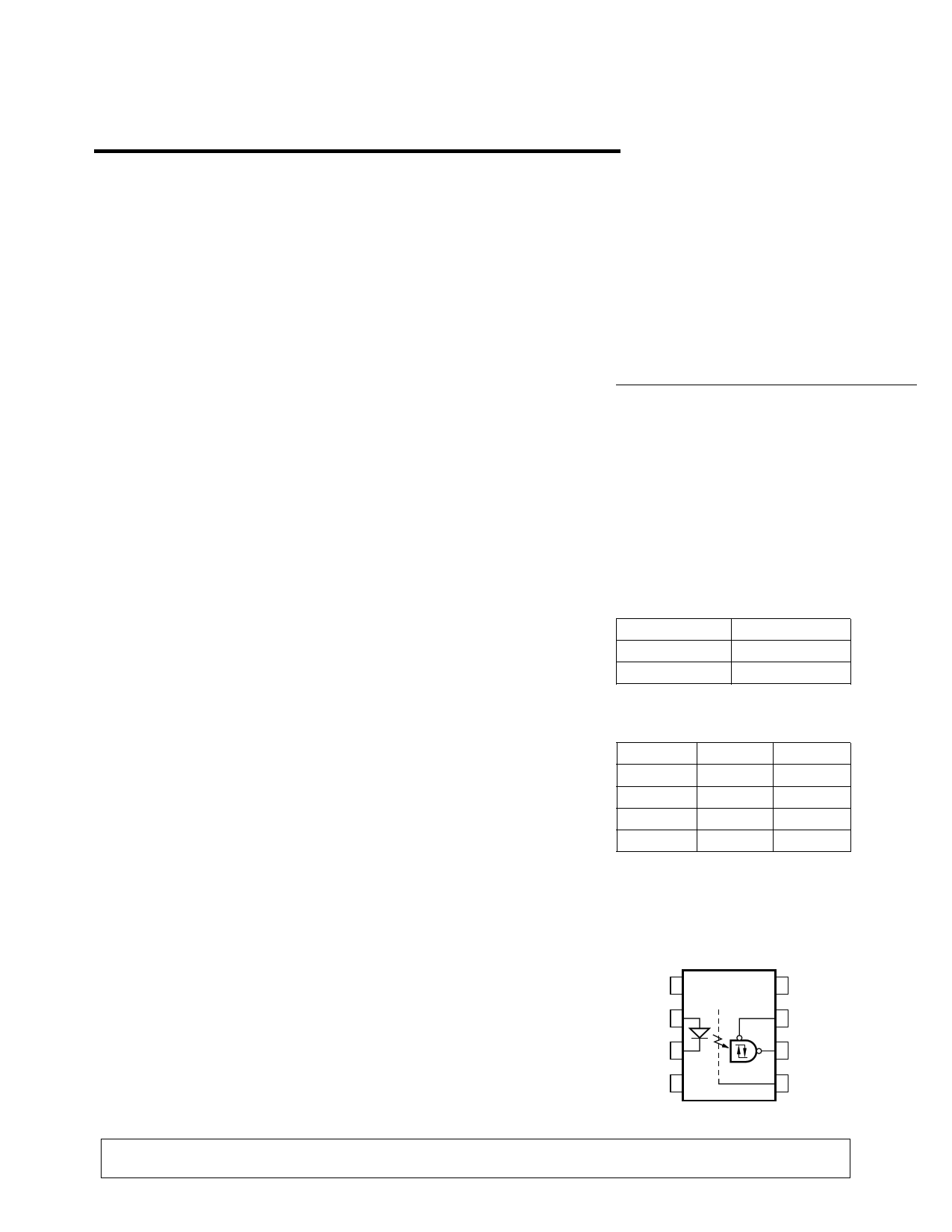
Functional Diagram
Multiple Channel Devices
Available
VCC
VE
VO
GND
CAUTION: It is advised that normal static precautions be taken in handling and assembly of this component to
prevent damage and/or degradation which may be induced by ESD.
1-524
5965-3004E
1 page 
Absolute Maximum Ratings
(No derating required up to +125°C)
Storage Temperature Range, TS .................................. -65°C to +150°C
Operating Temperature, TA ......................................... -55°C to +125°C
Case Temperature, TC ................................................................ +170°C
Junction Temperature, TJ .......................................................... +175°C
Lead Solder Temperature .............................................. 260°C for 10 s
Average Forward Current, IF AVG (each channel) ........................ 10 mA
Peak Input Current, IF PK (each channel) ............................... 20 mA[1]
Reverse Input Voltage, VR (each channel) ....................................... 3 V
Supply Voltage, VCC ............................................. 0.0 V min., 7.0 V max.
Average Output Current, IO ............................ -25 mA min., 25 mA max.
(each channel)
Output Voltage, VO (each channel) ..................... -0.5 V min., 10 V max.
Output Power Dissipation, PO (each channel) ........................... 130 mW
Package Power Dissipation, PD (each channel) ......................... 200 mW
Single Channel Product Only
Three State Enable Voltage, VE ........................... -0.5 V min., 10 V max.
8 Pin Ceramic DIP Single Channel Schematic
ANODE
CATHODE
VE
VO
Note enable pin 7. An external 0.01 µF to 0.1 µF bypass capacitor must be connected
between VCC and ground for each package type.
ESD Classification
(MIL-STD-883, Method 3015)
HCPL-5400/01 .................................................................. (∆∆ ), Class 2
HCPL-5430/31 and HCPL-6430/31 ................................. (Dot), Class 3
Recommended Operating Conditions
Parameter
Symbol Min.
Input Current (High)
Supply Voltage, Output
Input Voltage (Low)
Fan Out (Each Channel)
IF(ON)
VCC
VF(OFF)
N
6
4.75
–
–
Max.
10
5.25
0.7
5
Units
mA
V
V
TTL Loads
Single Channel Product Only
High Level Enable Voltage
Low Level Enable Voltage
VEH
VEL
2.0 VCC
0 0.8
V
V
1-528
5 Page 
MIL-PRF-38534 Class H,
Class K, and DESC SMD
Test Program
Hewlett-Packard’s Hi-Rel Opto-
couplers are in compliance with
MIL-PRF-38534 Classes H and K.
Class H devices are also in
compliance with DESC drawings
5962-89570, and 5962-89571.
Testing consists of 100% screen-
ing and quality conformance
inspection to MIL-PRF-38534.
Data Rate and Pulse-
Width Distortion
Definitions
Propagation delay is a figure of
merit which describes the finite
amount of time required for a
system to translate information
from input to output when
shifting logic levels. Propagation
delay from low to high (tPLH)
specifies the amount of time
required for a system’s output to
change from a Logic 0 to a Logic
1, when given a stimulus at the
input. Propagation delay from
high to low (tPHL) specifies the
amount of time required for a
system’s output to change from a
Logic 1 to a Logic 0, when given
a stimulus at the input (see
Figure 5).
When tPLH and tPHL differ in
value, pulse width distortion
results. Pulse width distortion is
defined as |tPHL - tPLH| and
determines the maximum data
rate capability of a distortion-
limited system. Maximum pulse
width distortion on the order of
25-35% is typically used when
specifying the maximum data rate
capabilities of systems. The exact
figure depends on the particular
application (RS-232, PCM, T-1,
etc.).
These high performance opto-
couplers offer the advantages of
specified propagation delay (tPLH,
tPHL), and pulse width distortion
(|tPLH -t PHL|) over temperature
and power supply voltage ranges.
Applications
VCC1 = +5 V
DATA
IN
A
GND 1
1
226 Ω 30 pF
HCPL-5400
VCC
274 Ω
TOTEM
POLE
OUTPUT GATE
(e.g. 54AS1000)
GND
Y=A
0.1 µF
VCC2 = 5 V
TTL
LSTTL
STTL
HCMOS
DATA
OUT
Y
GND 2
2
Figure 13. Recommended HCPL-5400 Interface Circuit.
1-534
11 Page | ||
| Páginas | Total 12 Páginas | |
| PDF Descargar | [ Datasheet HCPL-6430.PDF ] | |
Hoja de datos destacado
| Número de pieza | Descripción | Fabricantes |
| HCPL-6430 | Hermetically Sealed/ Very High Speed/ Logic Gate Optocouplers | Agilent(Hewlett-Packard) |
| HCPL-6431 | Hermetically Sealed/ Very High Speed/ Logic Gate Optocouplers | Agilent(Hewlett-Packard) |
| HCPL-643K | Hermetically Sealed/ Very High Speed/ Logic Gate Optocouplers | Agilent(Hewlett-Packard) |
| HCPL-643X | Hermetically Sealed/ Very High Speed/ Logic Gate Optocouplers | Agilent(Hewlett-Packard) |
| Número de pieza | Descripción | Fabricantes |
| SLA6805M | High Voltage 3 phase Motor Driver IC. |
Sanken |
| SDC1742 | 12- and 14-Bit Hybrid Synchro / Resolver-to-Digital Converters. |
Analog Devices |
|
DataSheet.es es una pagina web que funciona como un repositorio de manuales o hoja de datos de muchos de los productos más populares, |
| DataSheet.es | 2020 | Privacy Policy | Contacto | Buscar |