|
|
|
PDF HCPL0730 Data sheet ( Hoja de datos )
| Número de pieza | HCPL0730 | |
| Descripción | Dual Channel Low Input Current/ High Gain Optocouplers | |
| Fabricantes | Agilent(Hewlett-Packard) | |
| Logotipo | ||
Hay una vista previa y un enlace de descarga de HCPL0730 (archivo pdf) en la parte inferior de esta página. Total 12 Páginas | ||
|
No Preview Available !
Dual Channel Low Input
Current, High Gain
Optocouplers
Technical Data
H
HCPL-2730 HCPL-0730
HCPL-2731 HCPL-0731
Features
• High Current Transfer Ratio
– 1800% Typical
• Low Input Current
Requirements – 0.5 mA
• Low Output Saturation
Voltage – 0.1 V
• High Density Packaging
• Performance Guaranteed
over Temperature
0°C to 70°C
• LSTTL Compatible
• High Output Current –
60 mA
• Safety Approval
UL Recognized - 2500 V rms
for 1 Minute and
5000 V rms* for 1 minute
CSA Approved
• Available in 8 Pin DIP and
SO-8 Footprint
• MIL-STD-1772 Version
Available (HCPL-5730/5731)
• Surface Mount Gull Wing
Option Available for 8-Pin
DIP (Option 300)
Applications
• Digital Logic Ground
Isolation
• Telephone Ring Detector
• Level Shifting
• EIA RS-232C Line Receiver
• Polarity Sensing
• Low Input Current Line
Receiver - Long Line or Party
Line
• Microprocessor Bus
Isolation
• Current Loop Receiver
• Line Voltage Status Indicator
-Low Input Power
Dissipation
Description
These dual channel optocouplers
contain a separated pair of GaAsP
light emitting diodes optically
coupled to a pair of integrated
high gain photo detectors. They
provide extremely high current
transfer ratio and excellent input-
output common mode transient
immunity. A separate pin for the
photodiodes and first gain stages
(VCC) permits lower output satura-
tion voltage and higher speed
operation than possible with
conventional photodarlington
type optocouplers. In addition,
VCC may be as low as 1.6 V
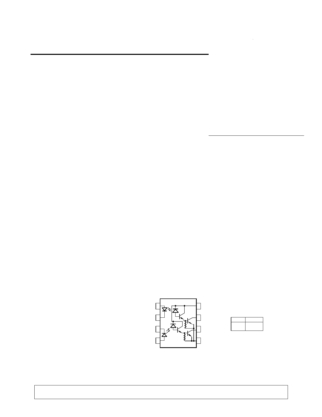
Functional Diagram
ANODE 1 1
CATHODE 1 2
CATHODE 2 3
ANODE 2 4
8 VCC
7 VO1
6 VO2
5 GND
TRUTH TABLE
LED
VO
ON LOW
OFF HIGH
*5000 V rms/1 minute withstand voltage rating is for Option 020 (HCPL-2730, HCLP-2731) products only.
A 0.1 µF bypass capacitor connected between pins 5 and 8 is recommended.
CAUTION: It is advised that normal static precautions be taken in handling and assembly of this component to
prevent damage and/or degradation which may be induced by ESD.
1-108
5965-3597E
1 page 
Small Outline SO-8 Package (HCPL-0731/HCPL-0730)
8765
3.937 ± 0.127
(0.155 ± 0.005)
XXX
YWW
1234
5.842 ± 0.203
(0.236 ± 0.008)
TYPE NUMBER
(LAST 3 DIGITS)
DATE CODE
0.381 ± 0.076
(0.016 ± 0.003)
1.270 BSG
(0.050)
5.080 ± 0.127
(0.200 ± 0.005)
7°
45°
X
0.432
(0.017)
3.175 ± 0.127
(0.125 ± 0.005)
1.524
(0.060)
0.228 ± 0.025
(0.009 ± 0.001)
DIMENSIONS IN MILLIMETERS (INCHES).
LEAD COPLANARITY = 0.10 mm (0.004 INCHES).
0.152 ± 0.051
(0.006 ± 0.002)
0.305 MIN.
(0.012)
Solder Reflow Temperature Profile (HCPL-073X and Gull Wing Surface Mount Option 300 Parts).
260
240
220
200 ∆T = 115°C, 0.3°C/SEC
180
160
∆T = 145°C, 1°C/SEC
140
120
100
80
60 ∆T = 100°C, 1.5°C/SEC
40
20
0
0 1 2 3 4 5 6 7 8 9 10 11 12
TIME – MINUTES
Note: Use of nonchlorine activated fluxes is highly recommended.
Regulatory Information
The HCPL-2731/2730 have been
approved by the following
organizations:
UL
Recognized under UL 1577,
Component Recognition
Program, File E55361.
CSA
Approved under CSA Component
Acceptance Notice #5, File CA
88324.
1-112
5 Page 
60 IF = 5.0 mA
IF = 4.5 mA
IF = 4.0 mA
IF = 3.5 mA
IF
IF
=
=
3.0
2.5
mA
mA
IF = 2.0 mA
30 IF = 1.5 mA
IF = 1.0 mA
IF = 0.5 mA
TA = 25° C
0 VCC = 5.0 V
01 2
VO – OUTPUT VOLTAGE – V
Figure 1. DC Transfer Characteristics.
2500
VCC = 5.0 V
VO = 0.4 V
2000
1500
1000
TA = 0° C
TA = 25° C
TA = 70° C
TA = 85° C
TA = -40° C
500
0
0.1 1.0 10
IF – FORWARD CURRENT – mA
Figure 2. Current Transfer Ratio vs.
Forward Current.
100
VCC = 5.0 V
VO = 0.4 V
10
TA = 85° C
TA = 25° C
TA = -40° C
1.0
0.1
0.1
1 10
IF – INPUT DIODE FORWARD CURRENT – mA
Figure 3. Output Current vs. Input
Diode Forward Current.
1000
100 IF
10 +
VF
–
1.0
TA = 25°C
0.1
0.01
0.001
1.1 1.2 1.3 1.4 1.5 1.6
VF – FORWARD VOLTAGE – V
100
TA = 25° C
10
HCPL-2731
VCC= 18 V
1.0
0.1
0.1
HCPL-2730
HCPL-2731
VCC = 7 V
1.0 10 100
IF – INPUT DIODE FORWARD CURRENT – mA
100 IF
T
0
VO
1.5 V
5V
tPHL VOL
10
HCPL-2731/0731
IF = 0.5 mA
RL= 4.7 kΩ
50 µs
1.0
0.1
0.01
HCPL-2730/0730
HCPL-2731/0731
IF = 1.6 mA
RL= 2.2 kΩ
TA = 25° C
0.1 1.0 10
T – INPUT PULSE PERIOD – ms
Figure 4. Input Diode Forward
Current vs. Forward Voltage.
Figure 5. Supply Current per
Channel vs. Input Diode Forward
Current.
Figure 6. Propagation Delay to Logic
Low vs. Pulse Period.
36
33 HCPL-2731/0731
30
(IF = 0.5 mA, RL = 4.7 kΩ)
HCPL-2730/0730
27 (IF = 1.6 mA, RL = 2.2 kΩ)
24
21 tPHL
18
15
tPLH
tPLH
12
9
6
3 tPHL
0
0 10 20 30 40 50 60 70 80 90
TA – TEMPERATURE – °C
Figure 7. Propagation Delay vs.
Temperature.
1-118
70 VCC = 5 V
60 TA = 25° C
50
tPHL RL= 2.2 kΩ OR 4.7 kΩ
40
30
tPLH RL= 4.7 kΩ
20
tPLH RL= 2.2 kΩ
10
0
02
46
8 10
IF – INPUT DIODE FORWARD CURRENT – mA
Figure 8. Propagation Delay vs. Input
Diode Forward Current.
11 Page | ||
| Páginas | Total 12 Páginas | |
| PDF Descargar | [ Datasheet HCPL0730.PDF ] | |
Hoja de datos destacado
| Número de pieza | Descripción | Fabricantes |
| HCPL0730 | Dual Channel Low Input Current/ High Gain Optocouplers | Agilent(Hewlett-Packard) |
| HCPL0730 | Low Input Current High Gain Split Darlington Optocouplers | Fairchild Semiconductor |
| HCPL0731 | Low Input Current High Gain Split Darlington Optocouplers | Fairchild Semiconductor |
| HCPL0738 | High Speed CMOS Optocoupler | Agilent(Hewlett-Packard) |
| Número de pieza | Descripción | Fabricantes |
| SLA6805M | High Voltage 3 phase Motor Driver IC. |
Sanken |
| SDC1742 | 12- and 14-Bit Hybrid Synchro / Resolver-to-Digital Converters. |
Analog Devices |
|
DataSheet.es es una pagina web que funciona como un repositorio de manuales o hoja de datos de muchos de los productos más populares, |
| DataSheet.es | 2020 | Privacy Policy | Contacto | Buscar |